
| |
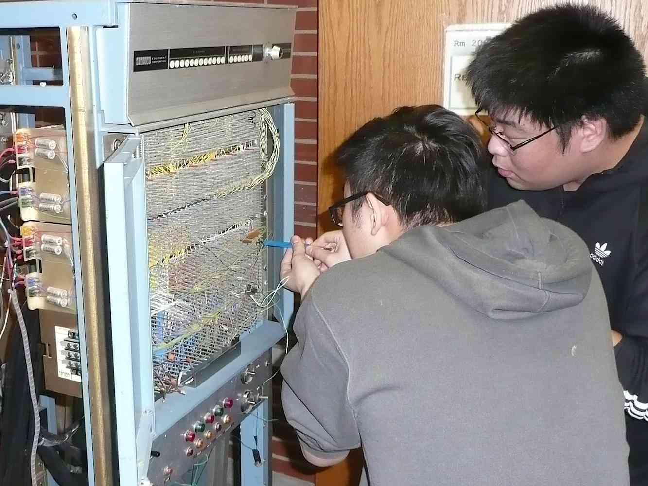
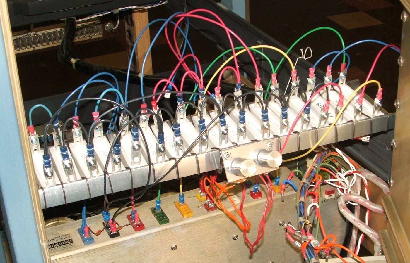
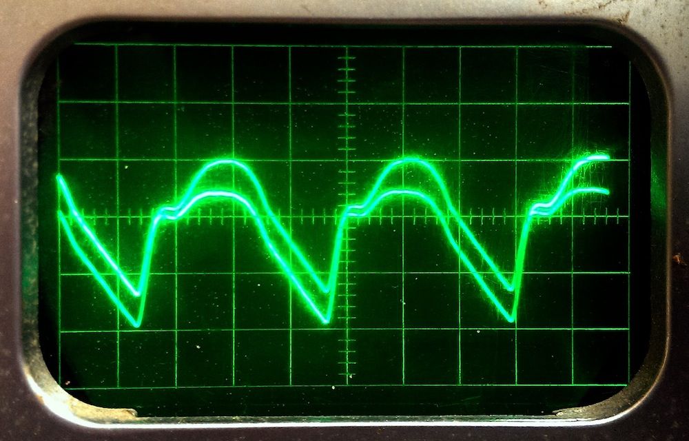
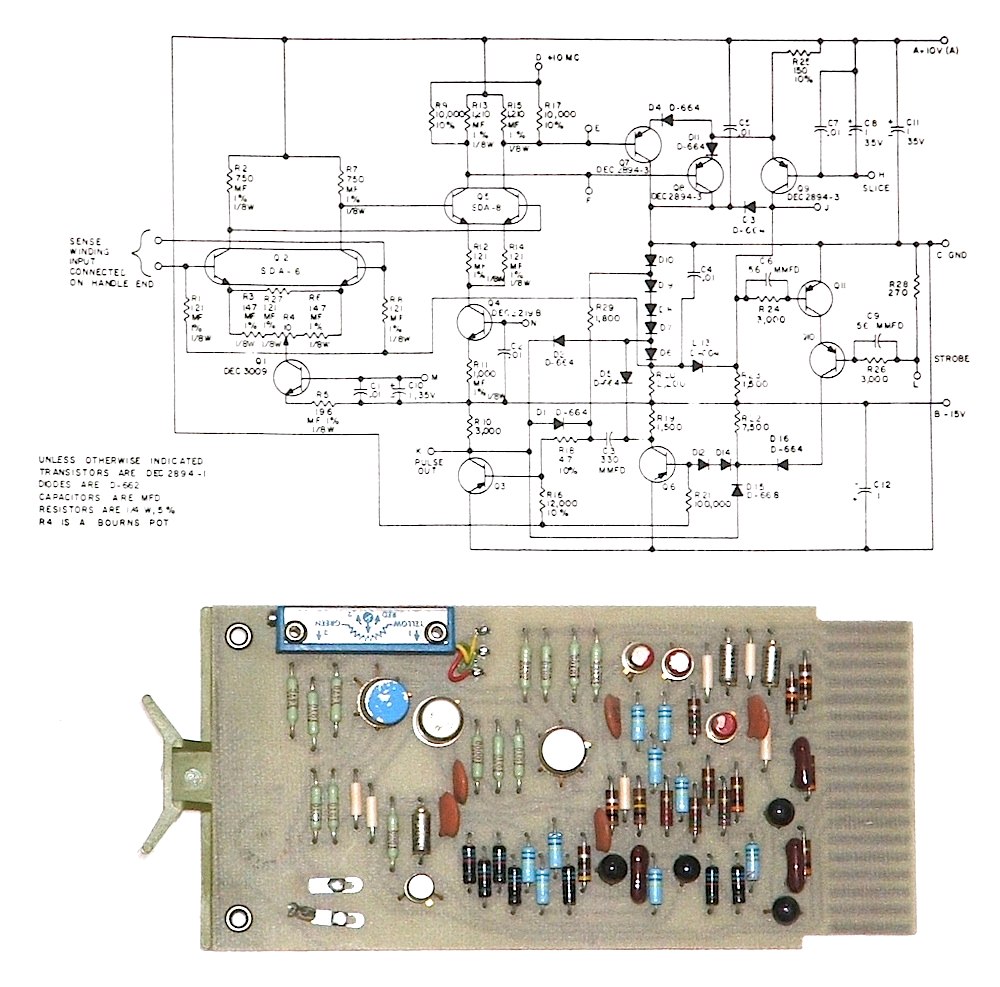
The University of Iowa's DEC PDP-8
Problem List
|
Contents, By System Component
- Computer Rack
- ADC Rack
- Teletype
- BRPE Paper-tape Punch
- Fairchild Tape Winder
- Other
Contents, By Bug Number
Introduction
This is a list of all of the problems encountered with
the University of Iowa's PDP-8 computer.
Problems are numbered sequentially in the order of discovery.
Click on any thumbnail image to see the full-sized image.
Bug 1: Broken handles on switch register
Front panel handle repair
|
|

|
|

|
|
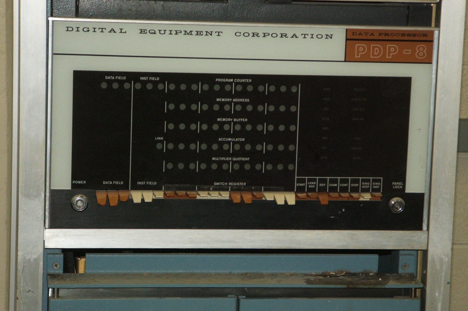
The plastic switch handles at the left end of the row of switches are
chipped, as if they collided with something. They feel loose, and it
is probable that the plastic ears that hinge some of these switch handles
to their switches have broken. Some of the switches may also need
rebuilding, as we did with Bug 44.
Bug 2: Loose cards on side of core memory
Loose cards
|
|
|
|
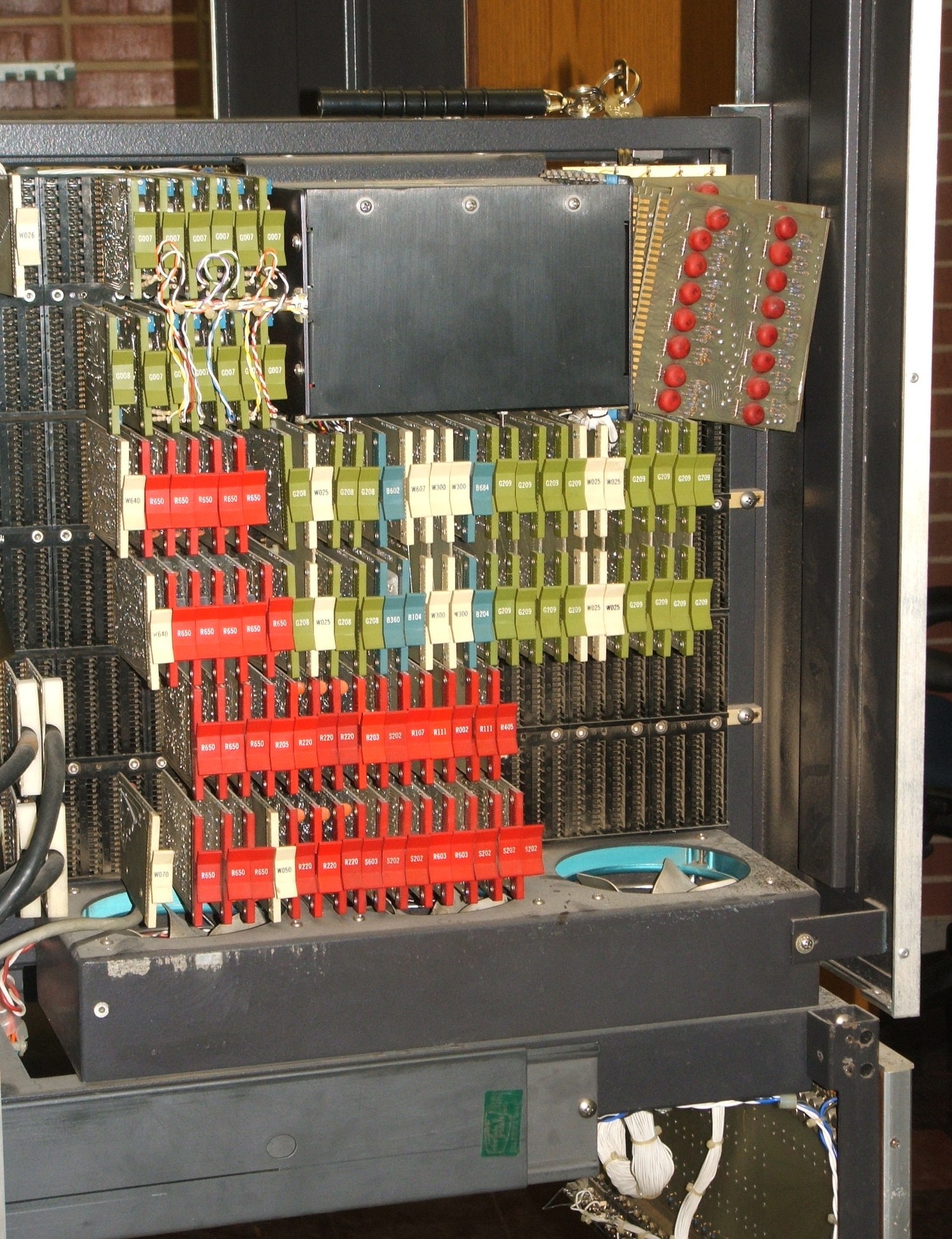
There are 8 card-edge connectors facing to the front on the side of the black
box holding the core memory. All but one of the circuit cards that
should be plugged into these connectors have fallen out.
Bug 3: Decayed foam strips in cabinet sides
Right side
|
|
|
|
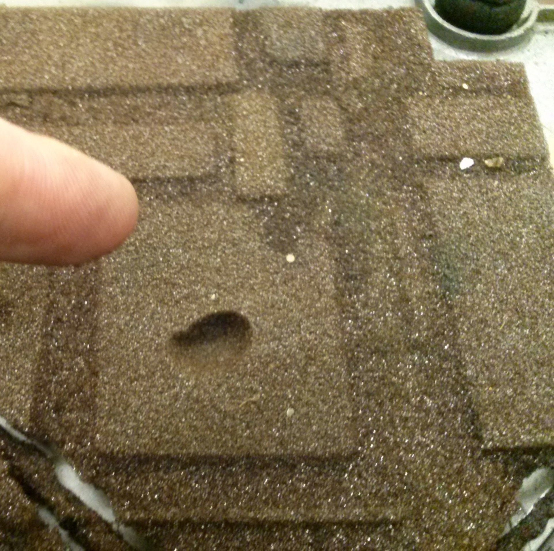
The front posts of the racks have aluminum channels holding plastic
foam weatherstrip against the cabinet skins. Whatever its purpose,
the foam in these channels has decayed.
It is brittle, and it crumbles when disturbed.
We will have to replace it with something less problematic.
The problem is similar to Bug 11, involving a foam
strip in an aluminum channel, but the dimensions are different.
Bug 4: Decayed ribbon cables between half-backplanes
Cable assembly
|
|
|
|
|
Cable connector
|
|
|
|
|
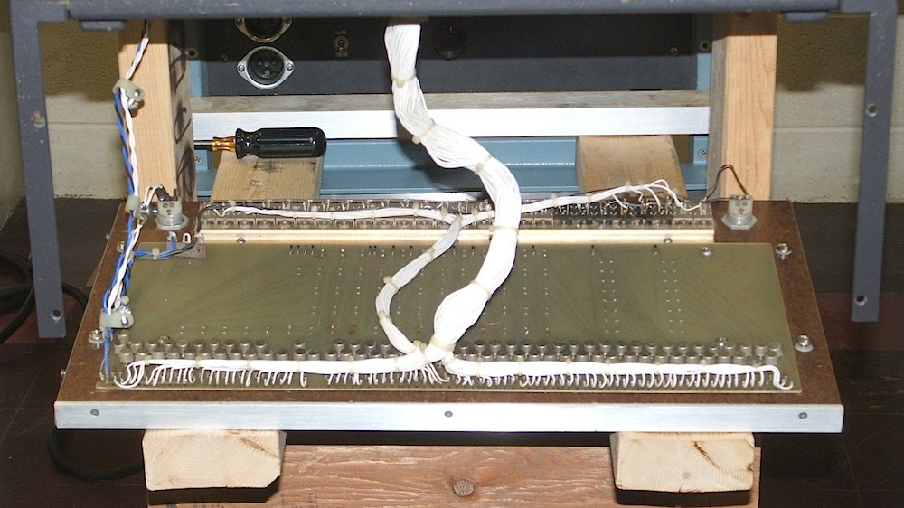
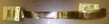
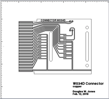
The ribbon cable assemblies that connect the left and right
half-backplanes of the machine are severely decayed.
The insulating layer on the two flex-print cable sthat make up each cable
assembly have turned to goo. We should find
an appropriate replacement material.
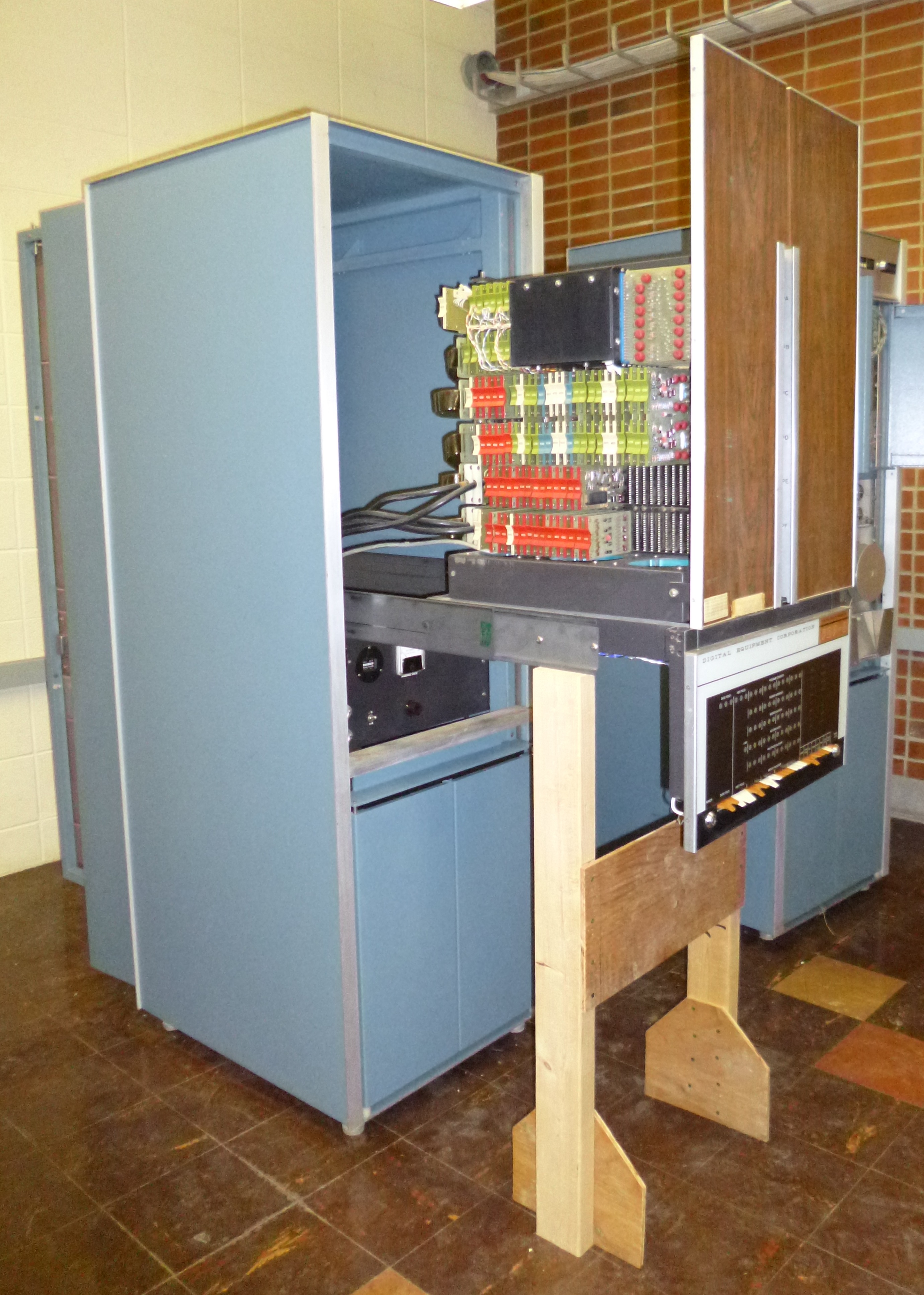
Bug 5: Stability of the computer rack
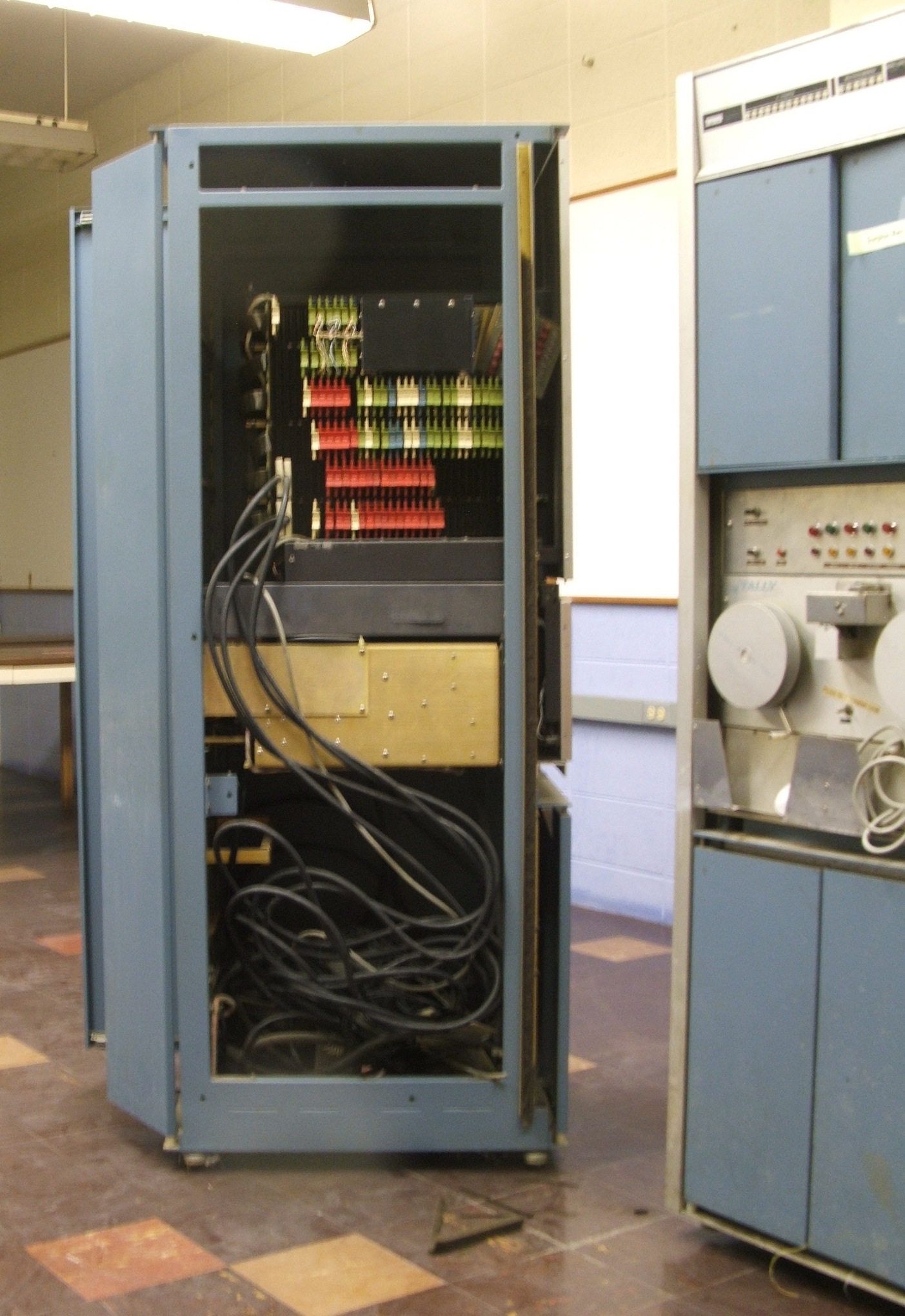
When the front panel with its lights and switches and the
entire computer is slid forward on its rack slides, the power supply and
rack are just barely balanced. The risk of the whole thing falling
over is significant.
- Noted Oct. 24, 2013.
- Noted Oct. 25, 2013.
Option of stabilizing leg(s) on attached table-top noted.
- Noted Oct. 28, 2013.
Note that the rack has leveling feet on the corners that have
a wider stance than the casters. These alone might suffice.
- Mitigated Jan. 23, 2014.
Leveling feet lowered to take weight off casters.
This provides only a small margin of safety when the computer
is extended from the rack!
- Solved temporarily
Feb. 05, 2014.
A wooden prop was made to support the weight of the fully
extended computer while the rack sides are removed for
access to the power supply. Replacing the table that was
formerly under the computer and had stabilizing feet would
be a better solution.
- Progress, Mar. 26, 2015.
The table originally on this PDP-8 resembles (but is smaller than)
the table on the surviving PDP-7 at the Living Computer Museum.
We got photos from them documenting the construction of that table.
- Progress, Sep. 27, 2019.
The Computer History Museum in Mountain View has a table from
a table-top PDP-8. They took extensive measurements of this table
for us. We suspect that the rack-mount table we need used most of
the same dimensions.
- Progress, Oct. 29, 2024.
Plans for reconstructing the table prepared.
Bug 6: Sticky latch for computer half backplanes
The latch
|
|
|
|
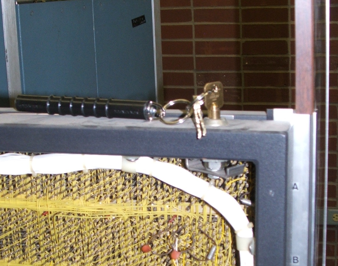
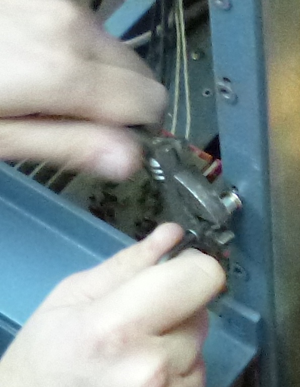
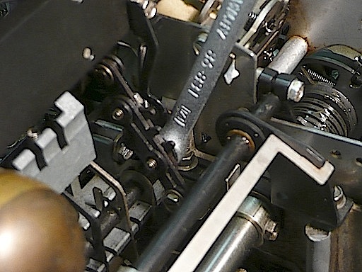
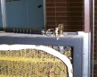
The latch that holds the half-backplanes of the computer in their
closed positions is very difficult to turn. The key is in the latch
in the photo.
The solution is to grasp the frames for the two half backplanes near the
lock with one hand and squeeze them together while turning the key
with the other hand. This releases the friction on the latch making it
easy to turn.
Bug 7: Broken paper-tape reader on Teletype
Broken reader
|
|
|
|
|
|
|
Repair in progress
|
|
|
|
|
|
|
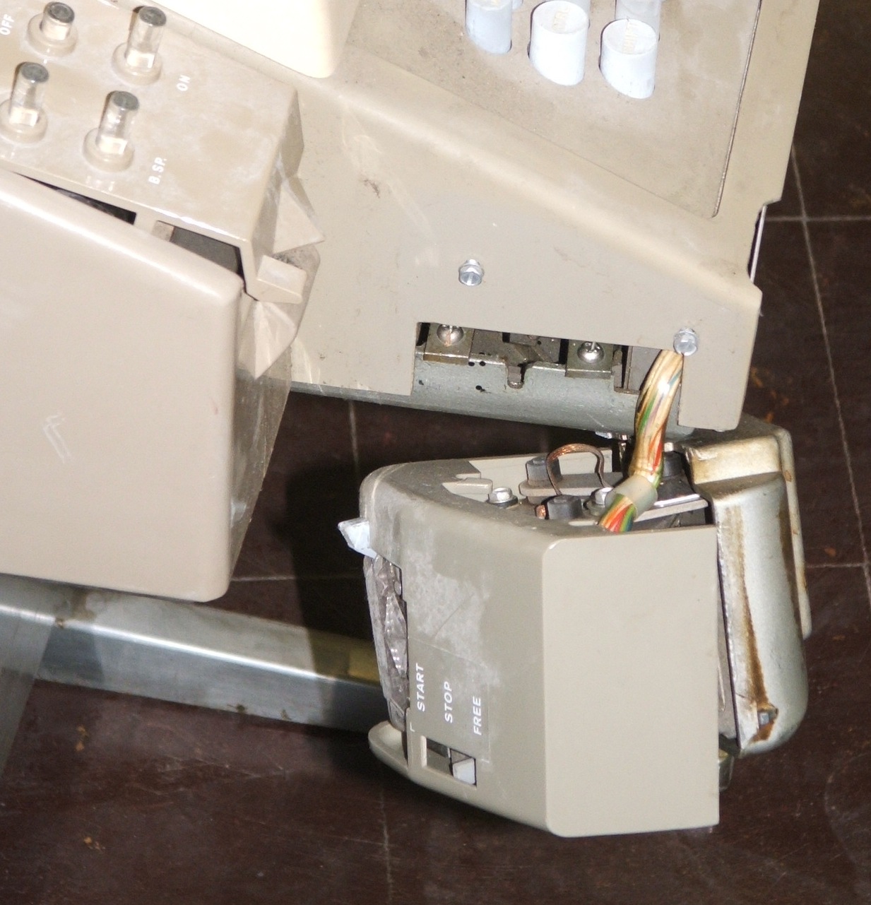
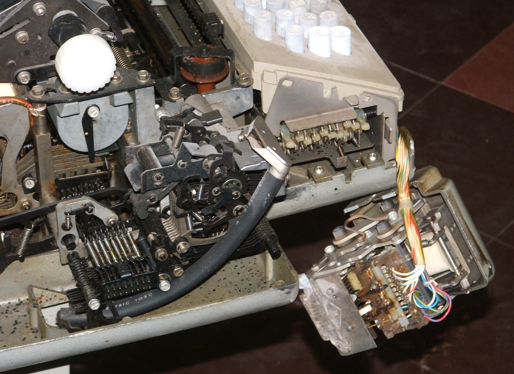
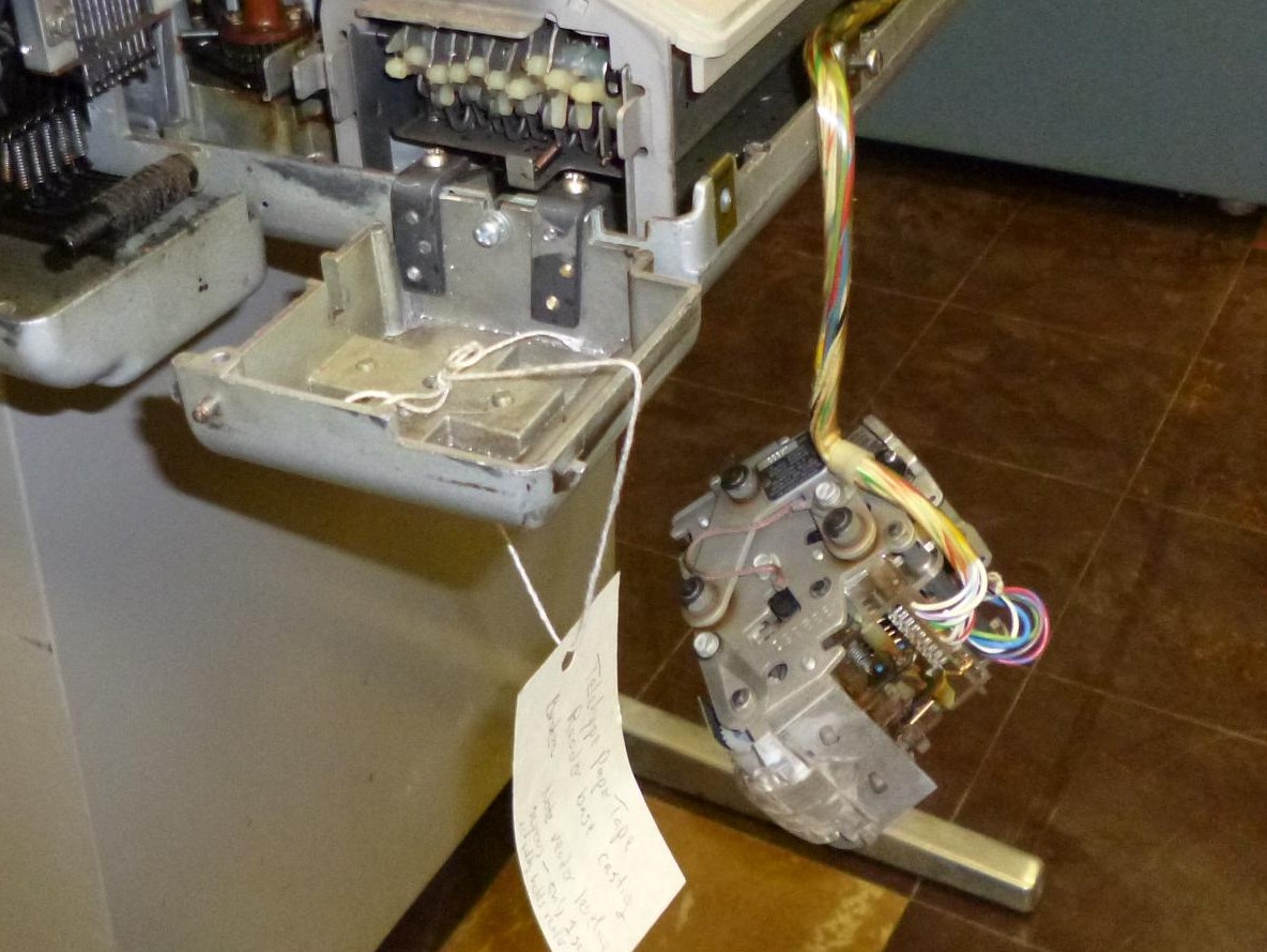
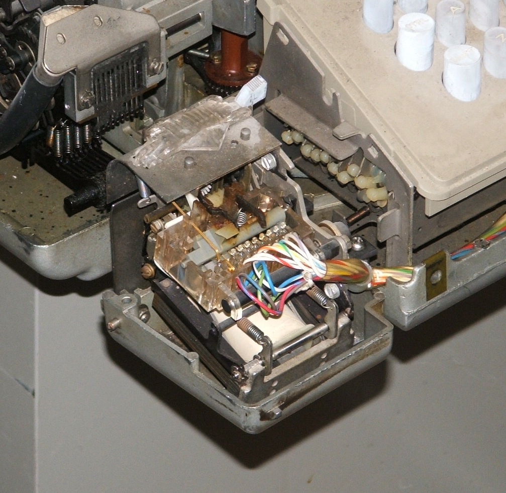
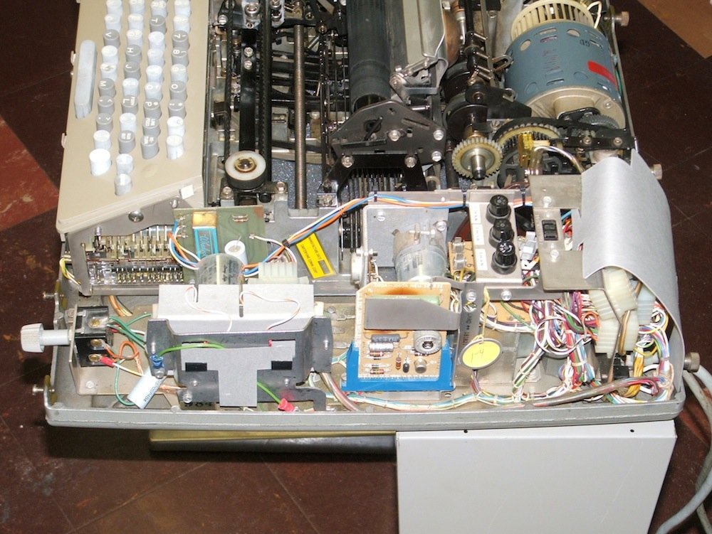
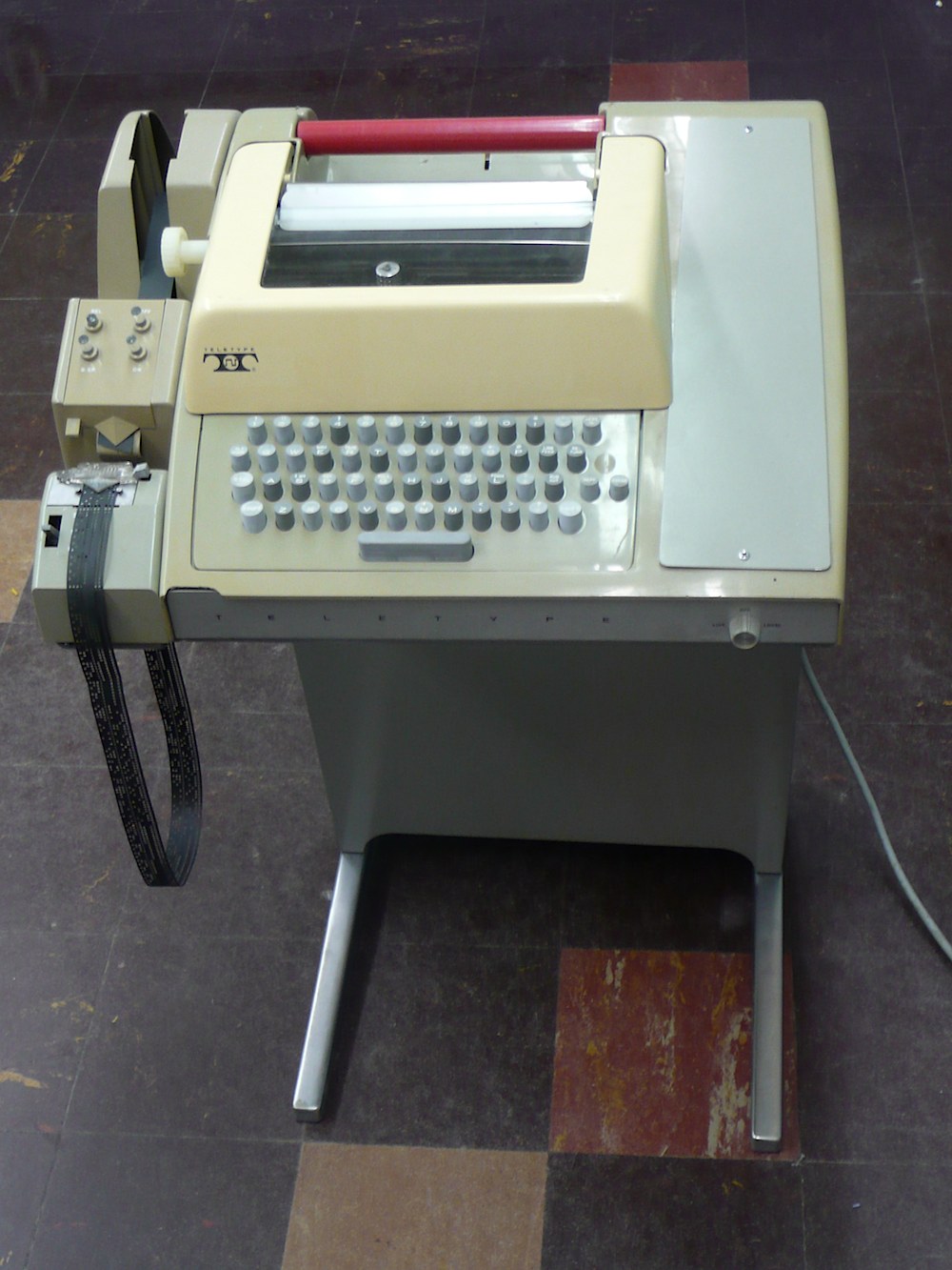
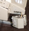
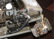
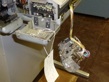
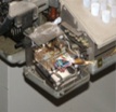
The paper-tape reader on the Teletype was broken.
The cast ears that attached the frame of the paper tape reader
to the frame of the Teletype broke off, probably when someone used
paper-tape reader as a handle to move the Teletype. Fortunately, these
could be replaced with home-made brackets. Also, the control lever
on the paper-tape reader was broken, probably in the same accident.
- Noted Oct. 25, 2013.
- Noted Nov. 25, 2013; plastic
covers and frame casting removed from reader.
- Noted Dec. 12, 2013; frame casting
taken home for repair.
- Partially resolved Dec. 16, 2013;
home-fabricated angle brackets added to replace broken ears on frame
casting, the frame casting was re-installed on the Teletype.
- Progress, Jan. 7, 2014;
reader re-installed on frame casting. Note that reader control
lever is broken; can we glue it?
- Progress, Feb. 19, 2014;
replaced broken reader control lever with new one;
didn't finish reader reassembly.
- Solved?, Feb. 20, 2014;
reader reassembled and mechanism tested.
Bug 8: Teletype power cord and data cables
Before and after
|
|
|
|
|
|
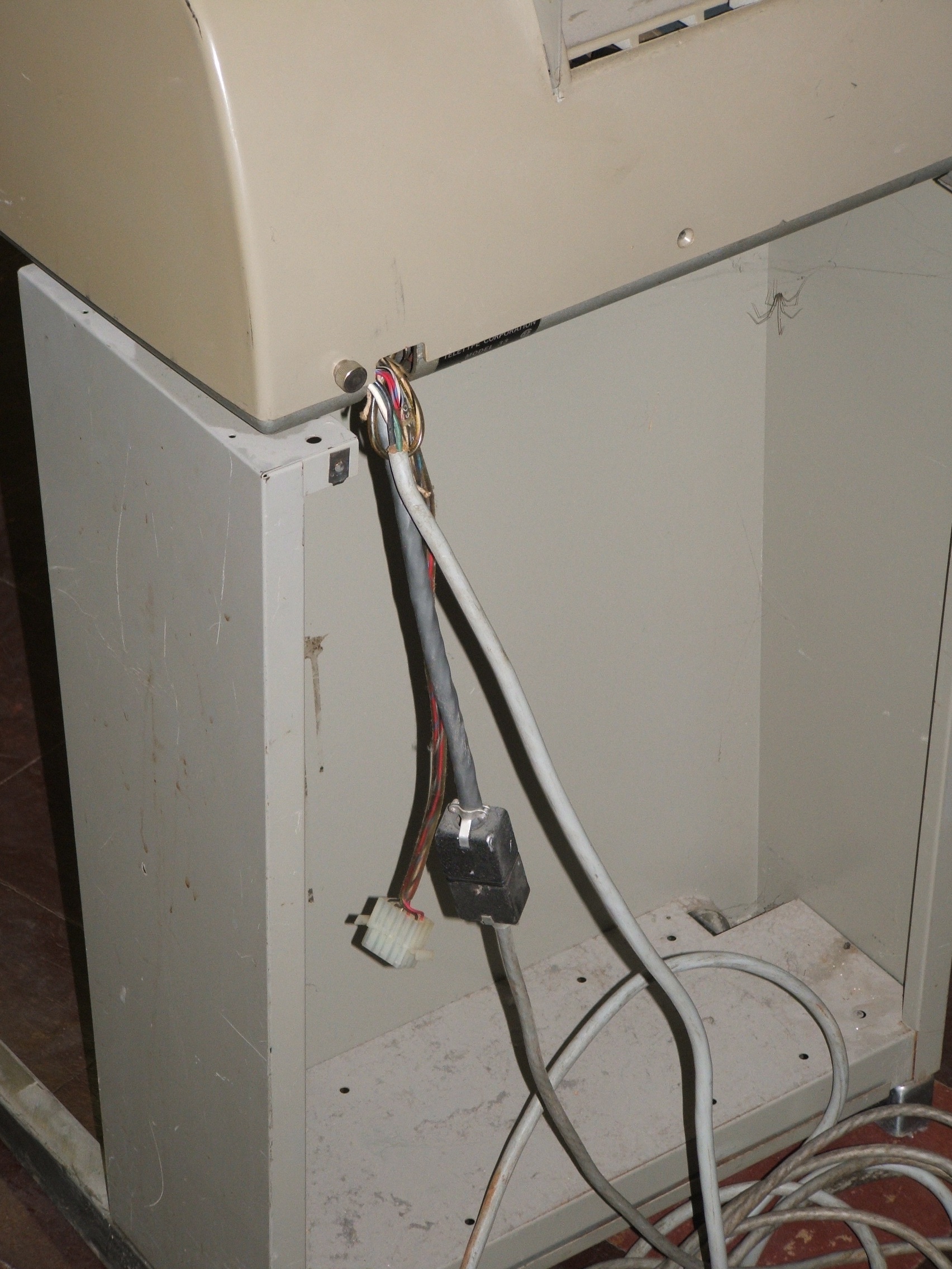
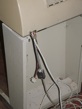
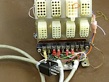
The electrical wires at the back of the Teletype were pulled out of their
strain reliefs and needed to be redone before anyone even thinks
about plugging it in. Also, there seems to be an extra data cable.
- Noted Oct. 25, 2013.
- Noted Nov. 4, 2013;
Bug 14 and Bug 15 should
be addressed at the same time.
- Partially resolved Nov. 25, 2013;
the power cord was carefully pushed back into its strain relief
and the unknown extra cable was folded up into the case.
The data cable remains in need of proper strain relief.
- Solved, May. 1, 2014.
Repaired data cable installed with new strain relief.
Questions about extra data cable remain unresolved.
- Noted Sep. 9, 2014.
Created Bug 38; the extra cable is for a power supply.
Bug 9: Teletype print hammer
Old and replaced hammer
|
|

|
|
|
|
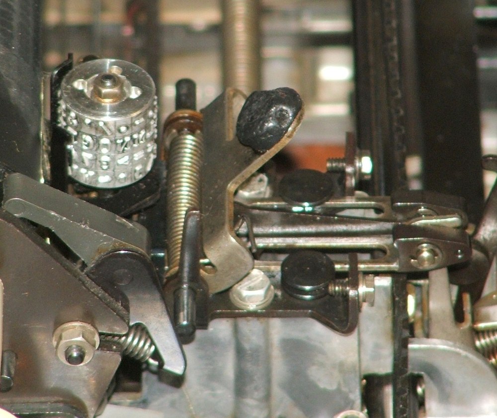
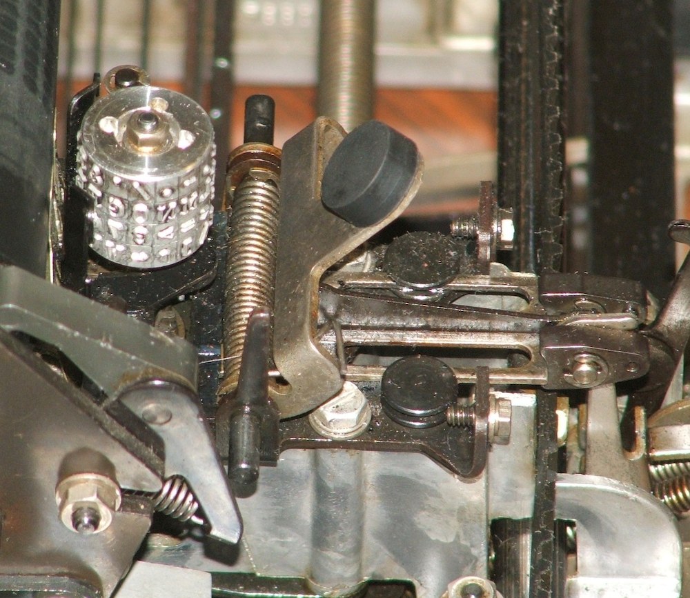
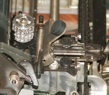
The rubber head on the Teletype print hammer was shot.
For many years, the standard fix among Teletype collectors has been
to replace the rubber with a piece of vinyl tubing, but recently,
a serious collector has manufactured new replacement hammer heads.
Bug 10: Reform electrolytic capacitors
Power supplies
|
|
|
|
|
|
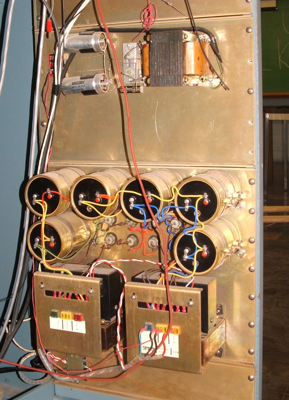
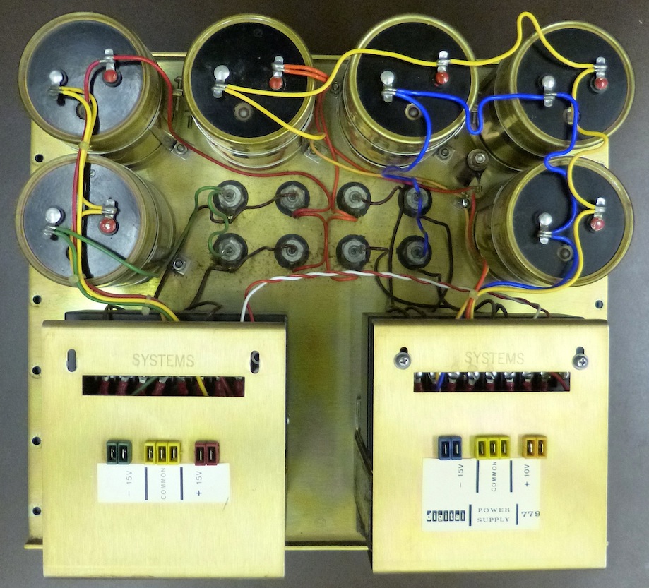
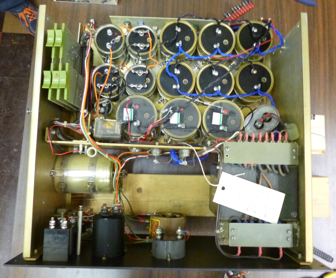
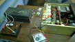
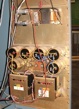
The electrolytic capacitors in the power supplies need reforming.
- Noted Oct. 28, 2013.
- Noted Jan. 23, 2014.
Necessary tools and supplies acquired.
- Noted Feb. 10, 2014.
Decided to remove and partially disassemble PDP-8 power supply,
creating Bug 20.
- Progress, Feb. 11, 2014.
Removed PDP-8 power supply, began work reforming 10V capacitors.
- Noted Feb. 12, 2014.
10V capacitors reforming well.
- Noted Feb. 13, 2014.
10V capacitors reforming well.
- Progress, Feb. 14, 2014.
10V capacitors reformed.
- Noted Feb. 17, 2014.
Begin work on -15V capacitors.
- Noted Feb. 18, 2014.
C9 to C11 reforming well.
- Noted Feb. 19, 2014;
C9 to C11 reforming well.
- Progress, Feb. 20, 2014;
C9 to C11 reformed, begin work on C6 to C8.
- Noted Feb. 21, 2014;
C6 to C8 reforming well.
- Noted Feb. 24, 2014;
C6 to C8 reforming well.
- Noted Feb. 25, 2014;
C6 to C8 reforming well.
- Progress, Feb. 26, 2014;
C6 to C8 reformed, begin work on C1 to C4.
- Noted Feb. 27, 2014;
C1 to C4 reforming well.
- Noted Feb. 28, 2014.
C1 to C4 reforming well.
- Noted Mar. 2, 2014.
C1 to C4 reforming well.
- Noted Mar. 3, 2014.
C1 to C4 reforming well.
- Noted Mar. 4, 2014.
C1 to C4 reforming well.
- Noted Mar. 5, 2014.
C1 to C4 reforming well.
- Progress, Mar. 6, 2014.
C1 to C4 reformed, begin work on C5, C15 and C16.
- Noted Mar. 7, 2014.
C5, C15 and C16 reforming well.
- Noted Mar. 9, 2014.
C5, C15 and C16 reforming well.
- Noted Mar. 10, 2014.
C5, C15 and C16 reforming well.
- Progress, Mar. 11, 2014.
C5 reformed, C15 and C16 reforming, but one may be bad.
- Noted Mar. 12, 2014.
- Noted Mar. 13, 2014.
C16 reforming, C15 confirmed bad.
- Progress, Mar. 16, 2014.
C16 reformed, start work on capacitors in Teletype Call Control Unit.
- Noted Mar. 20, 2014.
TTY CCU caps reforming well, with replacement for C15.
- Noted Mar. 24, 2014.
TTY CCU cap reforming well, with replacement for C15.
- Partially solved, Mar. 27, 2014.
TTY CCU cap and replacement for C15 reformed!
This completes the reforming of the capacitors
in the Teletype and PDP-8 power supply.
- Noted Apr. 30, 2014.
Extract Type 779 power supply for reforming,
creating Bug 32.
- Noted Sept. 9, 2014.
Capacitors C1 to C3 reforming.
- Noted Sept. 10, 2014.
Capacitors C1 to C3 held at 25V.
- Progress, Sept. 18, 2014.
Capacitors C1 to C3 tested, not great but acceptable.
- Partially solved, Oct. 2, 2014.
Capacitors C4 to C6 tested, not great but acceptable.
This completes the reforming of the capacitors
in the Type 779 power supply.
- Noted Nov. 14, 2014.
Start work on the capacitor in the Teletype tape-reader supply.
- Progress, Dec. 1, 2014.
Change approach to the TR supply to get above 50 volts.
- Progress, Dec. 3, 2014.
Reforming voltage idling at 125V.
- Progress, Dec. 4, 2014.
Reforming voltage idling at 155V, but job only half done.
- Noted, Oct. 30, 2025.
Set up to reform high-speed reader-punch power supply,
creating Bug 79.
- Progress, Nov. 3, 2025
Reader-punch supply idles OK at 12.5V.
- Partially solved, Nov. 17, 2025
- Solved, Feb. 12, 2026
I/O rack power supplies all tested.
Bug 11: Decayed foam gasket in cabinet doors
Door gasket
|
|

|
|
The foam gaskets that seal the vertical edges of the rear plenum
door of each cabinet need renewal.
The problem is similar to Bug 3, involving a foam
strip in an aluminum channel, but the dimensions are different. Each door
has two gaskets, one on the latch side that is easy to see, and one on the
hinge side that is most apparent only when the door is open and the hinge-side
skin of the rack is removed.
Bug 12: Rebuild the Tally reader cable
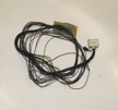
Tally reader cable
|
|
|
|
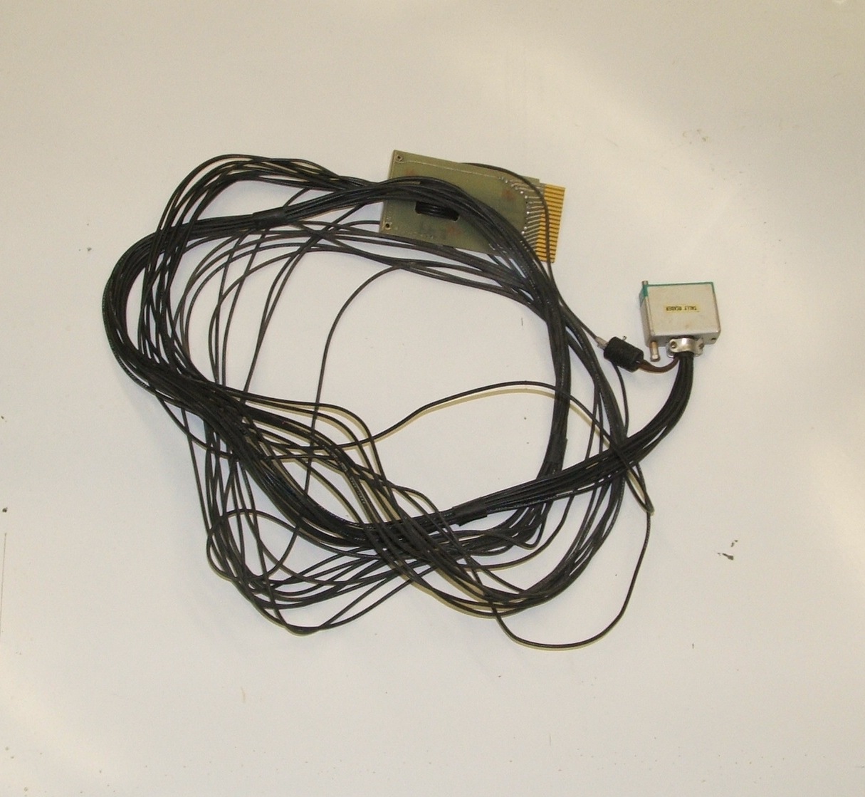
Where is the
Tally 424
reader interface that the card-edge connector on the
reader cable connects to? And, what slot in the reader interface?
As of the identification of this bug, the cable has been plugged into the
back of the Tally reader. Mapping of the 34D Scope display interface
revealed that this backplane segment at the bottom of the ADC rack includes
the high-speed reader interface. Unfortunately, on further investigation,
it turned out that the cable, while it may have originally served this
reader, had been extensively modified and had to be rebuilt.
- Noted Nov. 4, 2013.
- Solved, Nov. 22, 2013.
- Reopened, June 6, 2014.
- Reopened, June 24, 2025.
Reverse engineer old cable.
- Progress, Mar. 5, 2026.
Design new Tally cable.
- Progress, Mar. 12, 2026.
Start making modified W021 connector.
- Progress, Mar. 20, 2026.
Finish modified W021 connector, modify design.
- Solved! Mar. 26, 2026.
Cable built, plugged in and tested.
- Reopened, July 21, 2026.
Data is inverted.
- Solved!, July 28, 2026.
Fixed data inversion,
created Bug 87 and Bug 88.
Bug 13: Make 110V power connection for Tally Reader
Dangling Jones plug
|
|
|
|
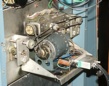
The 2-pin Jones plug on the back of the connector to the
Tally 424
paper tape reader appears to be intended to bring power to the reader's drive
motor. We verified this, and then made the appropriate secondary cable to
bring 110V power from the power distribution panel on the ADC rack to this
plug.
Bug 14: Repair or replace Teletype data cable
Cable repair
|
|
|
|
The Teletype data cable was cut between the W070 connector to the computer
and the 12-pin Jones plug at the back of the Teletype. The bad parts near the
ends of the cable were cut out and the salvaged remainder was reinstalled
with a 6-pin Jones plug at the point where the cable had been cut.
The resulting cable is shorter than the original, but with the jones plug
at the point of the cut, an extension cable can easily be added.
Bug 15: Inappropriate Teletype data connector
Inappropriate plug
|
|
|
|
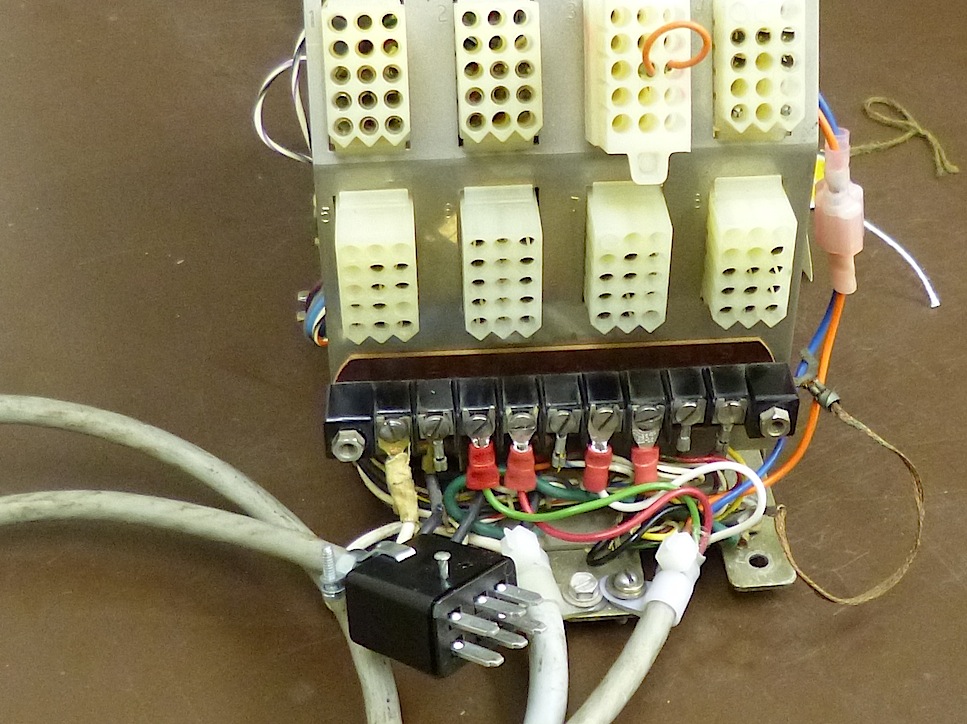
The 12-pin Jones plug in the Teletype cable was not really appropriate.
By 1970, DEC was using an 8-pin in-line Mate-n-Lok connector at this
point, but (as evidenced by the 12-pin connector here), earlier DEC users
who wanted a plug in their cables frequently used Jones plugs.
6-pin Jones plugs are still available, so we installed one.
- Noted Nov. 4, 2013, along with
Bug 8 and Bug 14.
- Noted Mar. 6, 2014.
New 6-pin Jones plugs acquired to replace 12-pin plugs.
- Noted Mar. 20, 2014.
Completed reverse engineering of cable, proposal for connector pinout.
- Progress, Mar. 27, 2014.
Old connector discarded; start installing replacement.
- Solved, May. 1, 2014.
New connector installed on cable to Teletype and W070 board.
Bug 16: Check and repair 110V rack wiring
Cut power wires
|
|
|
|
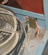
The power distribution wiring harness between the ADC Rack and the PDP-8 rack
was cut, close to the terminal strip at the right rear corner of the rack.
The power cabling for the both racks will need careful checking.
- Noted Nov. 7, 2013.
The cut end on the ADC rack was identified.
- Noted Feb. 10, 2014.
The other side of the cut was located in the CPU cabinet
and coiled out of the way.
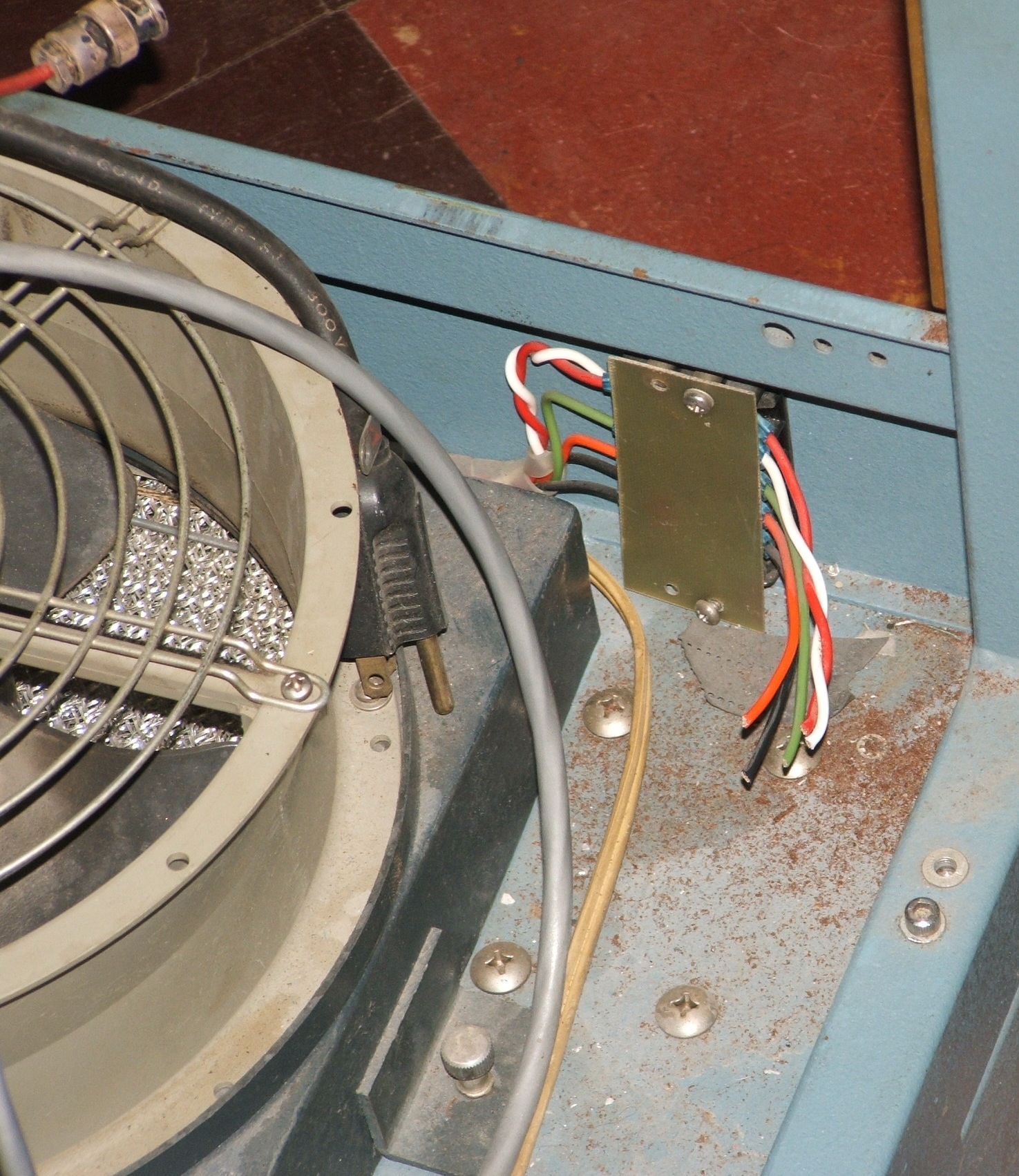
- Progress, Apr. 4, 2014 A bad wire
on one of the cooling fans was cut out and replaced. The plug
on the PDP-8 line cord was declared unsafe.
- Progress, Dec. 5, 2014.
We began work on the cable between the computer and ADC racks.
- Progress, Jan. 23, 2015.
Start reverse engineering the Type 834 power control panel.
- Progress, Jan. 27, 2015.
Mercury relay tested and documented.
- Progress, Jan. 30, 2015.
Unsafe rack wiring documented.
- Solved?, Feb. 2, 2015.
Wiring in PDP-8 rack fixed and tested,
creating Bug 43.
- Progress, Dec. 11, 2025.
Account for total load of all peripherals.
- Progress, Feb. 12, 2026.
All but power for paper-tape-reader done.
- Solved! Mar. 31, 2026.
Paper-tape-reader powered!
Bug 17: Teletype cover broken
|
|
| Broken cover, start repair
|
|---|
|
|
| Repair completed
|
|---|
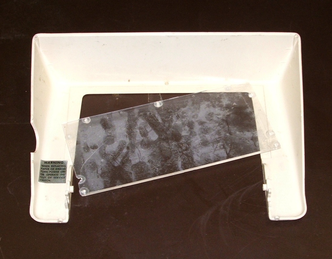
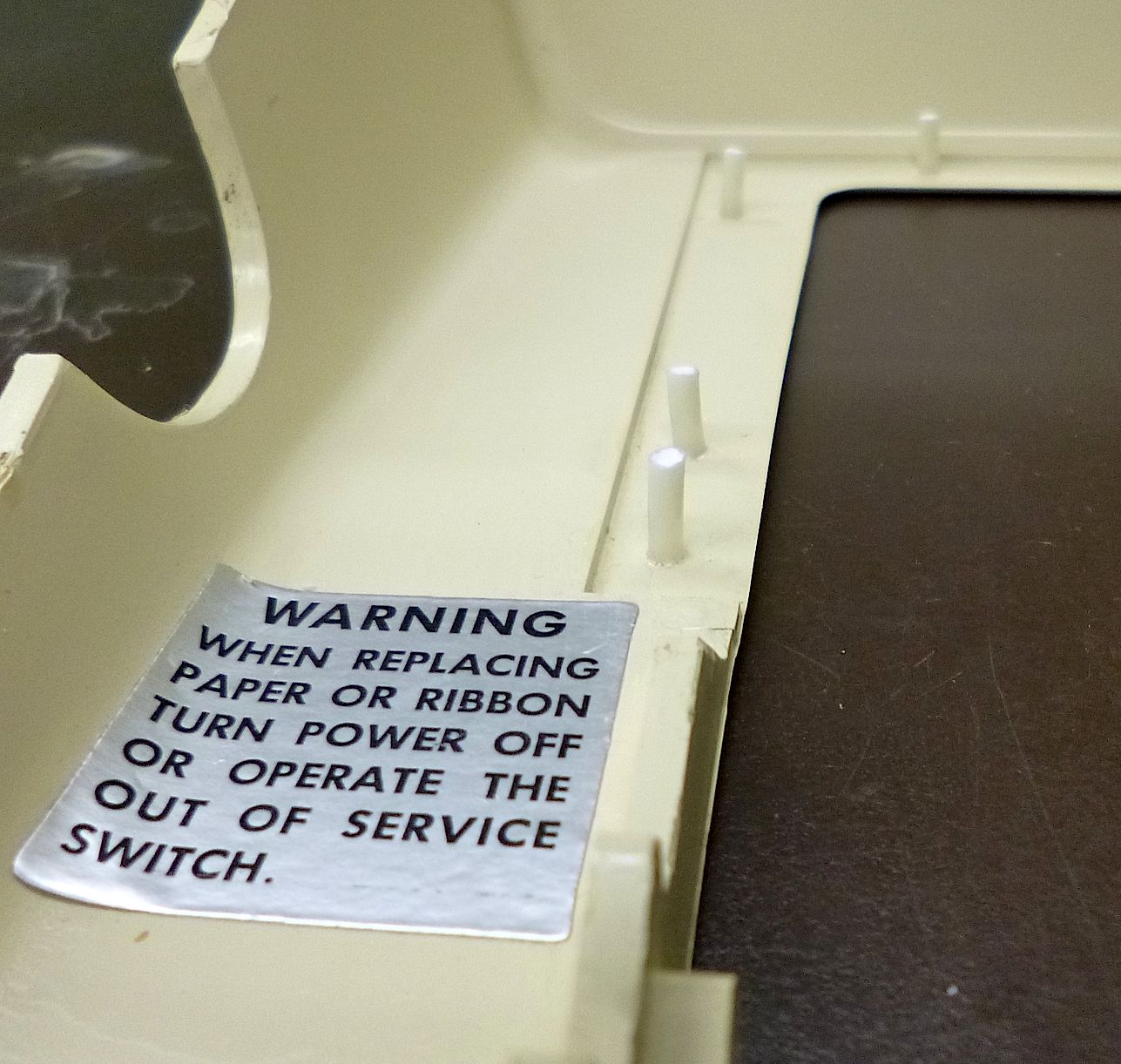
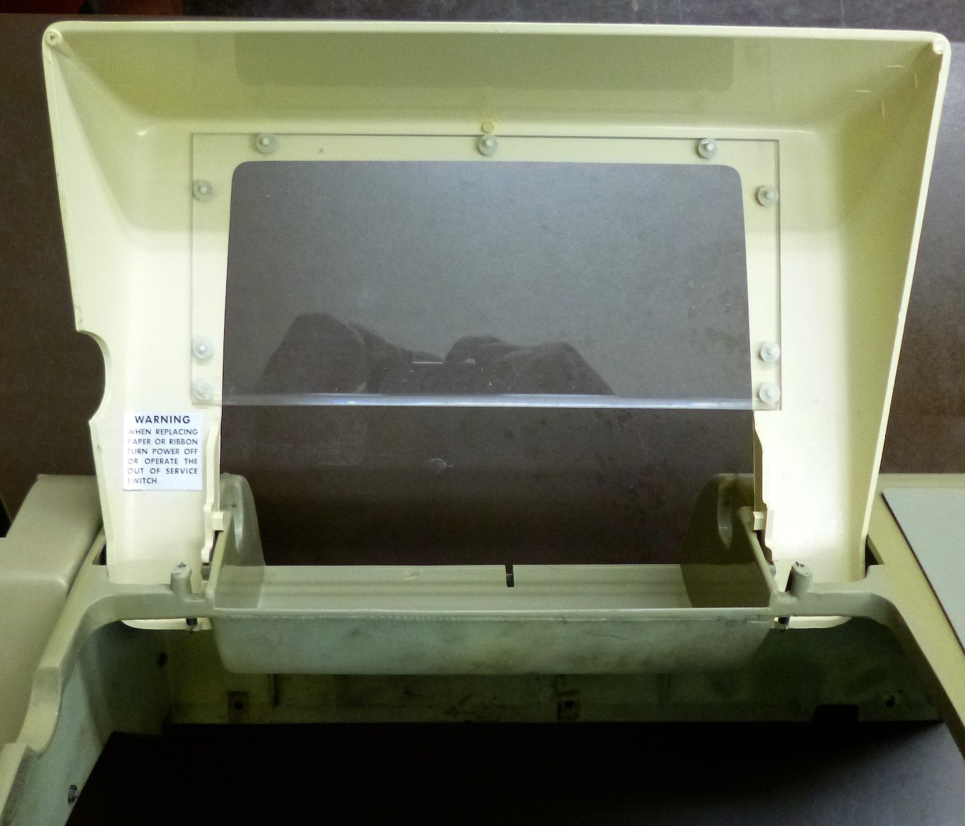
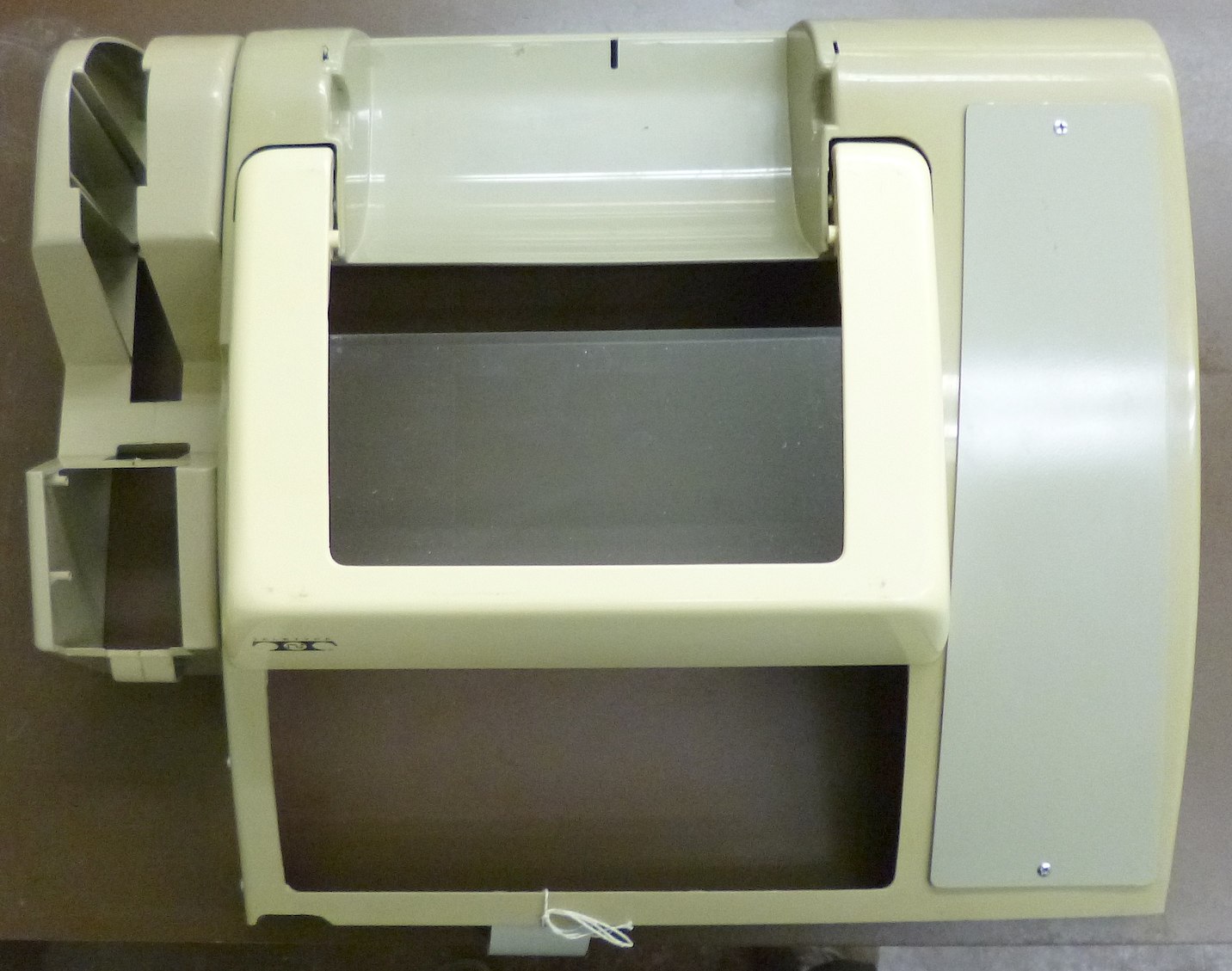
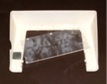
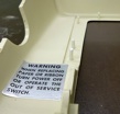
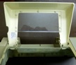
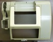
The transparent plastic insert in the Teletype cover was cracked and
entirely broken free
from its mounting. It appears that it was thermally riveted to the inside
of the cover. The whole cover was filthy, and
had a broken mounting ear. There are also cracks and broken mounting
fingers in other parts of the cover.
- Noted Nov. 25, 2013.
- Progress, Feb. 21, 2014.
New window manufactured.
- Progress, Feb. 24, 2014.
Started solvent-welding cracks and broken mounting
fingers in the ABS casing.
- Progress, Feb. 25, 2014.
Reinforced previously glued cracks with ABS splints.
- Progress, Feb. 27, 2014.
Replaced broken window-mounting studs in cover.
- Progress, Mar. 2, 2014.
Rebuilt broken left rear mounting ear in cover.
- Progress, Mar. 3, 2014.
Rebuilt mounting ear tested by mating cover with Teletype lid.
- Solved, Mar. 13, 2014.
Permanently attached new window, installed lid in Teletype cover.
Bug 18: Missing ADC plenum panel and screws
|
|
| ADC Plenum door
|
|---|
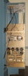
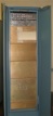
The rear plenum door of the ADC rack is missing one panel (the one below the
ADC interface panel) and about 20 screws. This admits dust and degrades the
effectiveness of the rack's cooling fan. A somewhat battered replacement
panel has been located -- original DEC manufacture, formerly part of PDP-9
serial number 120.
- Noted Dec. 12, 2013.
- Partially resolved Jan. 7, 2014;
the old PDP-9 panel was
patched and installed (temporarily with the wrong kind of screws).
- Solved, Apr. 14, 2014;
missing screws replaced.
Bug 19: Inventory and clean the computer backplanes
Preliminary backplane maps
|
|
|
|
|
|
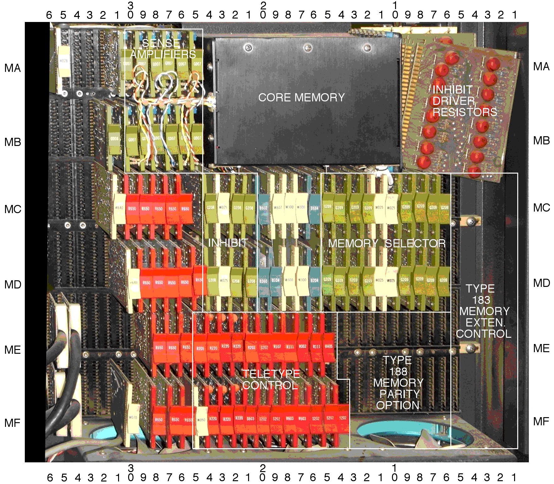
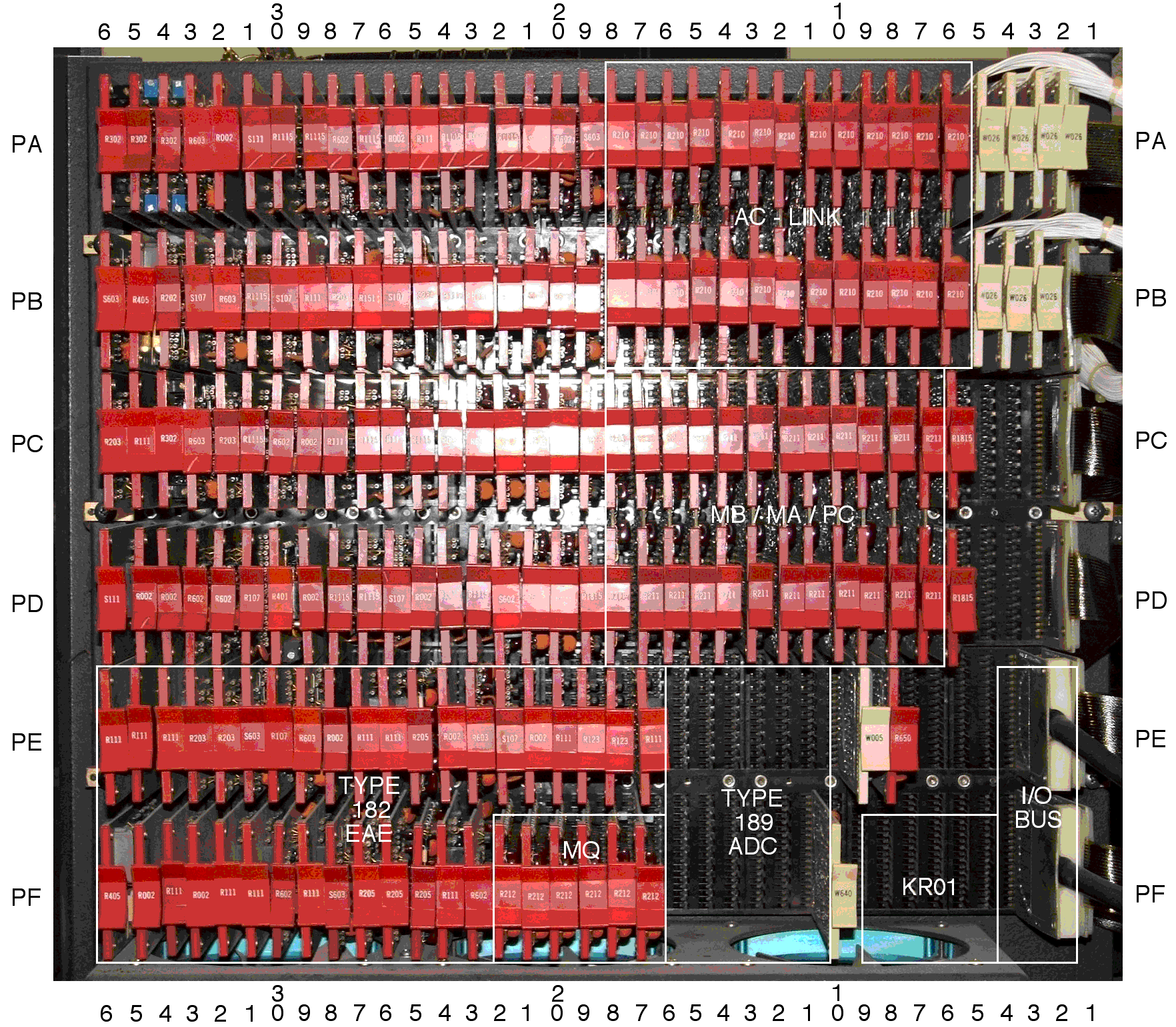
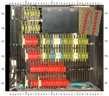
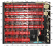
We need to inventory the boards in both backplanes, then remove them
and clean both the boards and the backplanes, and then re-insert the
boards where they came from. Wherever there are discrepancies between
the boards and the maintenance manuals, we will need to do more to figure
out how to put things right, suspecting boards might have been pulled and
replugged incorrectly over the years when this machine was not operational.
- Noted Jan. 23, 2014.
- Discrepancy found Mar. 24, 2014.
- Discrepancy found Apr. 29, 2014.
- Progress, Oct. 2, 2014.
Reverse engineering of the backplane begun in an effort to
resolve discrepancies.
- Progress, Jan. 22, 2015.
Exchanged three boards, eliminating all but one discrepancy.
- Progress, Jan. 27, 2015.
Resolved final discrepancy; need to document it.
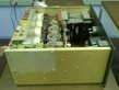
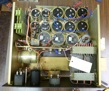
Bug 20: Repair and re-install PDP-8 power supply
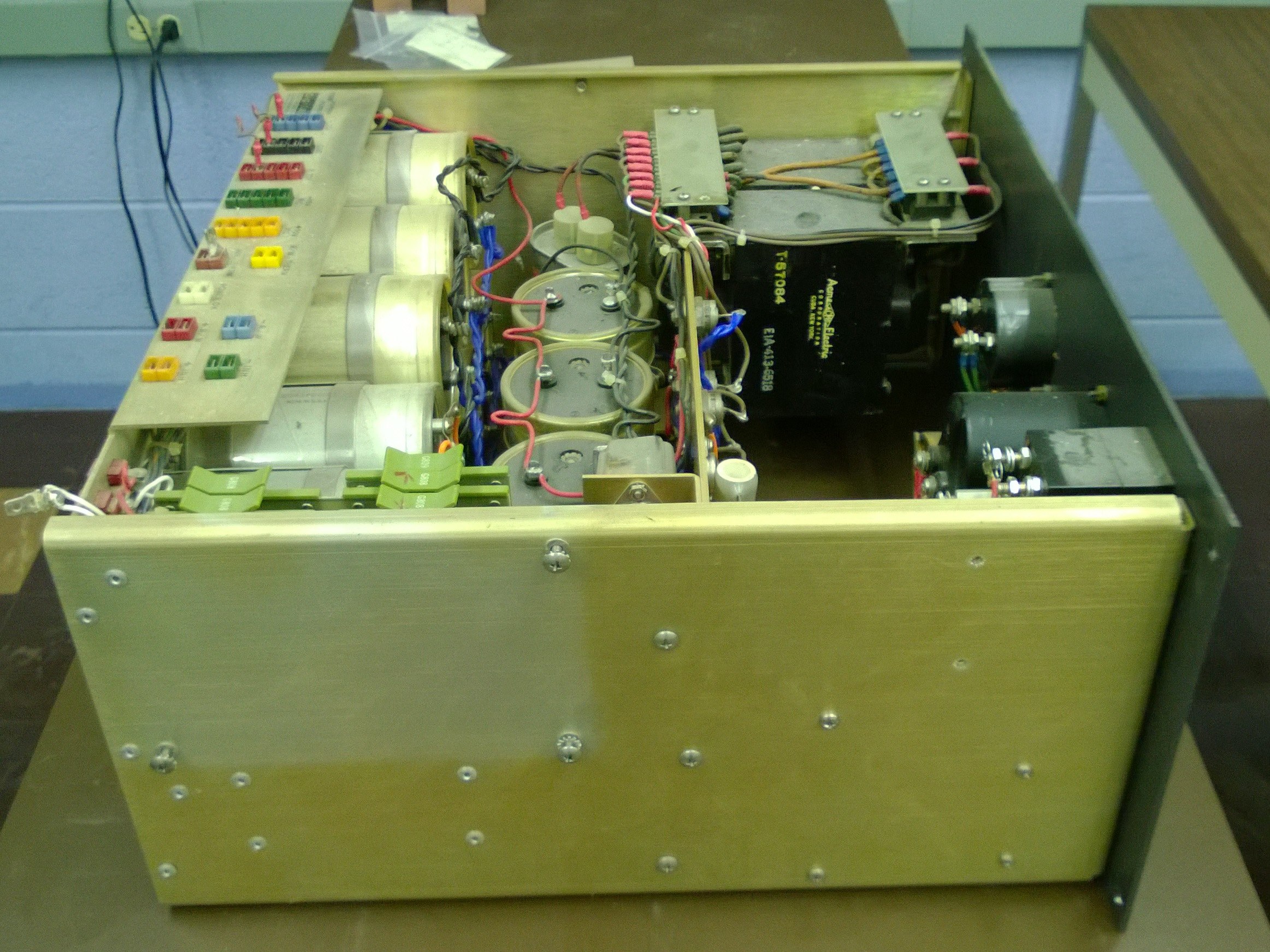
The supply out of the rack
|
|
|
|
|
|
|
Opened for access
|
|
|
|
|
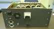
To allow reforming of the capacitors in the PDP-8 power supply
(see Bug 10),
the supply needed to be removed from the rack and partially disassembled.
- created, Feb. 10, 2014.
Wiring harness almost completely removed.
- Noted Feb. 11, 2014.
Supply moved to table.
- Further damage Feb. 13, 2014.
Rivets holding back panel to supply removed.
- Further damage Feb. 14, 2014.
Back panel eased out from side panels.
- Progress, Feb. 17, 2014.
Installed swage nuts to replace pop-rivets.
- Progress, Mar. 11, 2014.
Re-connected C5 and started reconnecting C6-11.
- Progress, Mar. 16, 2014.
C6-11 and C16 reconnected.
- Progress, Mar. 27, 2014.
New C15 installed, old C17 removed.
- Progress, Apr. 4, 2014.
New C17 installed.
- Progress, May 5, 2014.
Replacement power connector work begun.
- Solved?, May 6, 2014.
Power supply reassembled and installed, creating
Bug 33.
- Reopened Oct. 29, 2014, power-OK
signal never asserted.
- Progress, Nov. 12, 2014,
Transistors Q1 and Q2 verified good.
- Solved?, Nov. 18, 2014,
Boards were in wrong slots!
Bug 21: Bad foam rubber pad under Teletype typing unit
Decayed foam
|
|

|
|
|
New foam
|
|
|
|
|
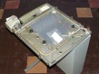
The foam rubber pad under the typing unit was decayed and crumbled
when disturbed.
This is Teletype part number 181138, pad,
pages 25 (drawing) and 32 (parts list) in
Parts Model 32 and 33 Page Printer Set, Teletype Corp.
Bulletin 1184B, Nov. 1964, change 5.
Bug 22: Bad vibration isolators in Teletype
Decayed rubber
|
|

|
|
The rubber grommets that serve as vibration isolators were decayed and
crumbled when disturbed.
This is part number 181109, mount, vibration,
pages 25 (drawing) and 32 (parts list) in
Parts Model 32 and 33 Page Printer Set, Teletype Corp.
Bulletin 1184B, Nov. 1964, change 5.
Bug 23: Missing Teletype sub-base mounting bolt
Base re-mounted
|
|
|
|
One teletype sub-base mounting bolt was missing.
and two more appear to have been inappropriate substitutes.
Bug 24: Missing Teletype call control unit screws
Two call control unit mounting screws were missing.
Bug 25: Clean, and de-gum the Teletype
The print head
|
|
|
|
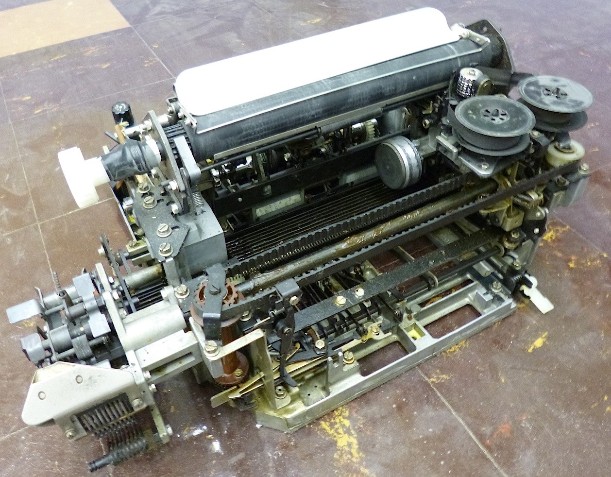
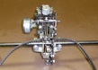
The Teletype mechanism was dirty and the old oil and grease has congealed
to an adhesive gum. For example, the print head carriage bearings were
so thorougly gummed that they would not rotate at all before several soakings
in WD-40. Cleaning these parts requirede nearly complete disassembly
of the machine.
- Noted Feb. 11, 2014.
- Progress, Feb. 21, 2014.
Keyboard degummed.
- Progress, Apr. 4, 2014.
Printer carriage degummed.
- Progress, Apr. 14, 2014.
Equivalent for KS7470 oil noted.
- Progress, Apr. 20, 2014.
Degumming largely complete.
- Progress, Nov. 15, 2016.
Degummed ribbon mechanism.
- Solved?, June. 22, 2017;
Platen removed, cleaned and reinstalled.
Bug 26: Re-assemble the Teletype
Major subassemblies
|
|
|
|
|
|
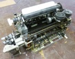
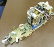
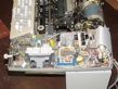
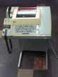
Cleaning and de-gumming the Teletype required large-scale disassembly,
so we need to put it back together.
- Noted Feb. 11, 2014.
- Progress, Mar. 7, 2014.
Keyboard reassembled, but needs lubrication.
- Progress, Apr. 29, 2014.
Typing unit reassembly started.
- Progress, Apr. 30, 2014.
Reassembly continues.
- Progress, May. 12, 2014.
Typing unit reassembled.
- Progress, Nov. 11, 2014.
Broke a screw, creating Bug 39.
- Progress, Dec. 3, 2014.
Paper tape punch reattached to typing unit.
Parts re-united
|
|
|
|
|
|
Reassembled
|
|
|
|
|
- Progress, Jan. 14, 2015;
All sub-base castings reunited and mounted on pedestal.
- Progress, Jan. 29, 2015;
Rebuild keyboard contact block.
- Progress, Feb. 02, 2015;
Keyboard reassembled and mounted to base.
- Progress, Feb. 04, 2015;
Call Control Unit mounted and wired.
- Progress, Feb. 16, 2015;
powered up, creating Bug 48,
Loose spring found.
- Progress, Mar. 30, 2015;
Loose spring misidentified, keyboard fixed?
- Progress, Apr. 2, 2015;
Loose spring correctly reinstalled.
- Progress, Nov. 15, 2016.
Reassembled and lubricated ribbon mechanism.
- Progress, Mar. 28, 2016.
Note status of reassembly.
- Solved!, May 17, 2019.
Reassembly completed!
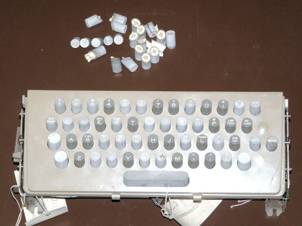
Bug 27: Teletype Keys are severely crazed
The keyboard, before and after
|
|

|
|
|
|
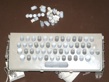
The Teletype keyboard keys were in very bad shape. The outer grey
layer of many keys has almost shattered into multiple fragments that
are not strongly attached to the white core of each key. Zoom in on
the photo for details. Can we buy or make new keys? Consider the
keys here that were made with laser-engraved acrylic filled with contrasting
paint, then laser cut and laminated to build up the required depth.
We eventually found a source of new-old-stock keys and replaced the
worst of the bad ones.
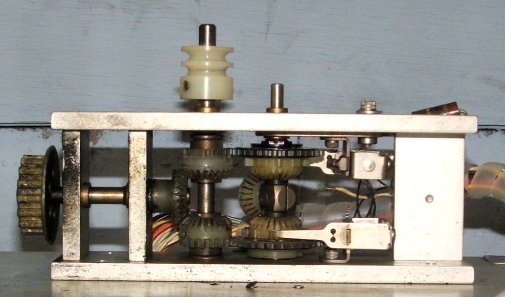
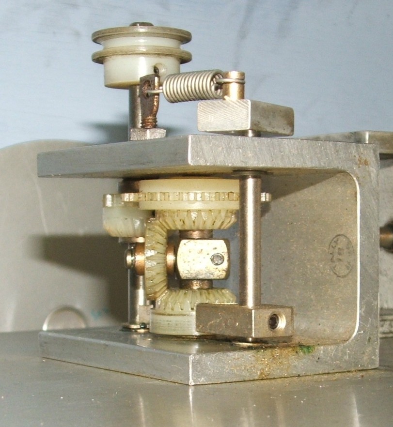
Bug 28: Clean and reassemble the Tally reader
Tally capstan and take-up reel drive
|
|
|
|
|
|
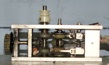
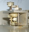
The
Tally 424
paper-tape reader mechanism needs to be properly lubricated.
This will require partial disassembly and reassembly of the reader.
Bug 29: Replace the Tally reader motor run capacitor
The capacitor and replacement
|
|
|
|
|
|
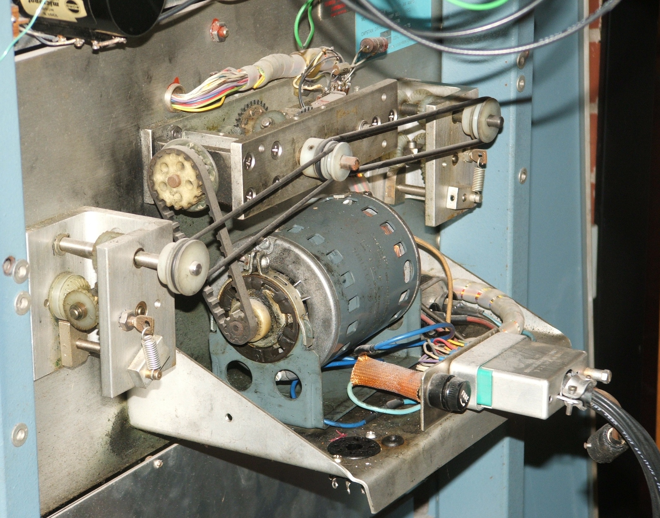
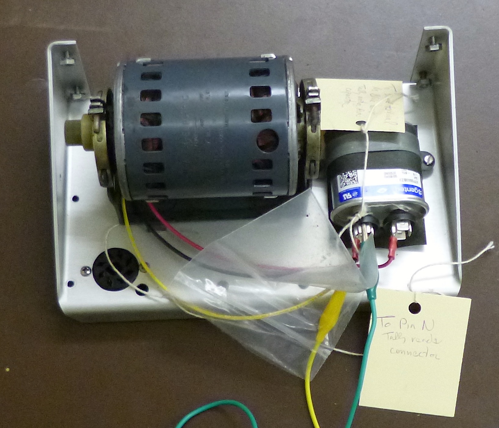
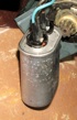
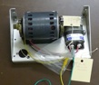
The
Tally 424
paper-tape reader motor uses a 3µF paper and oil capacitor.
Given the time period when this was made, it is almost certainly filled with
PCB oil and reports from others suggest that failures are not uncommon and
occasionally explosive. Therefore, it must be replaced.
Bug 30: Replace the Tally reader motor leads
The motor stator
|
|
|
|
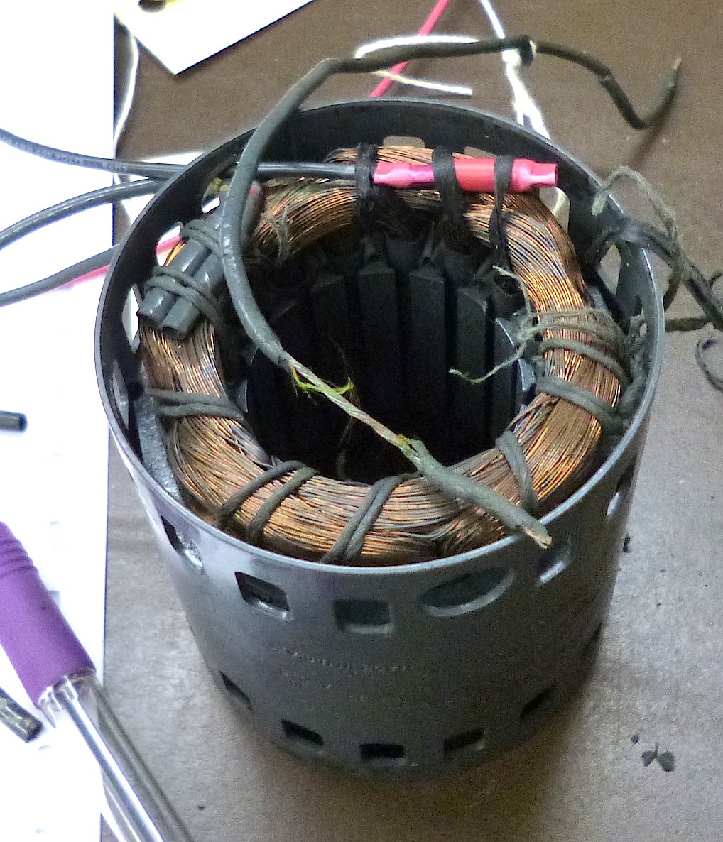
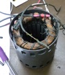
The power leads to the
Tally 424
paper-tape reader motor were in bad conditon and needed replacement.
Bug 31: Repair and Reconfigure ADC Rack
Installing a rivnut
|
|
|
|
|
Removing wiring
|
|
|
|
|
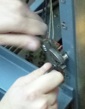
When the Psychology department mounted the Tally reader and magnetic tape
interface in spare spots in the ADC rack, they drilled out some of the rivnuts
DEC had installed and drilled (carelessly) some new holes. Before we
remount the Tally reader and any other peripherals in this rack, we should
replace the missing rivnuts. We will need to replace other missing parts of
this rack, and if we change the configuration of equipment in this rack,
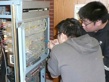
we may need to add new rivnuts. We also need to remove the wiring and
electronics for the peripherals we no-longer have.
- Progress, Apr. 29, 2014.
Missing rivnuts replaced.
- Progress, May 5, 2014.
New doorstop for top front doors.
- Progress, Feb. 14, 2018.
Remove wiring for mag-tape drive.
- Progress, Feb. 21, 2018.
Remove bulk of mag-tape drive interface. Parts remain in row D of the ADC
interface.
- Progress, July 17, 2026.
Make temporary power and bus connections to test ADC rack.
Bug 32: Reassemble Type 779 power supply
The supply
|
|
|
|
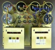
In order to reform the capacitors in the Type 779 power supply, it
had to be extracted from the ADC rack.
- created, Apr. 30, 2014.
Extract Type 779 power supply for reforming.
- Progress, Oct. 2, 2014.
Capacitors reformed, reassembly started.
- Solved, Oct. 9, 2014.
Supply reassembled, tested and put back in the ADC rack.
Bug 33: Test Type 708 power supply
Dummy load
|
|
|
|
|
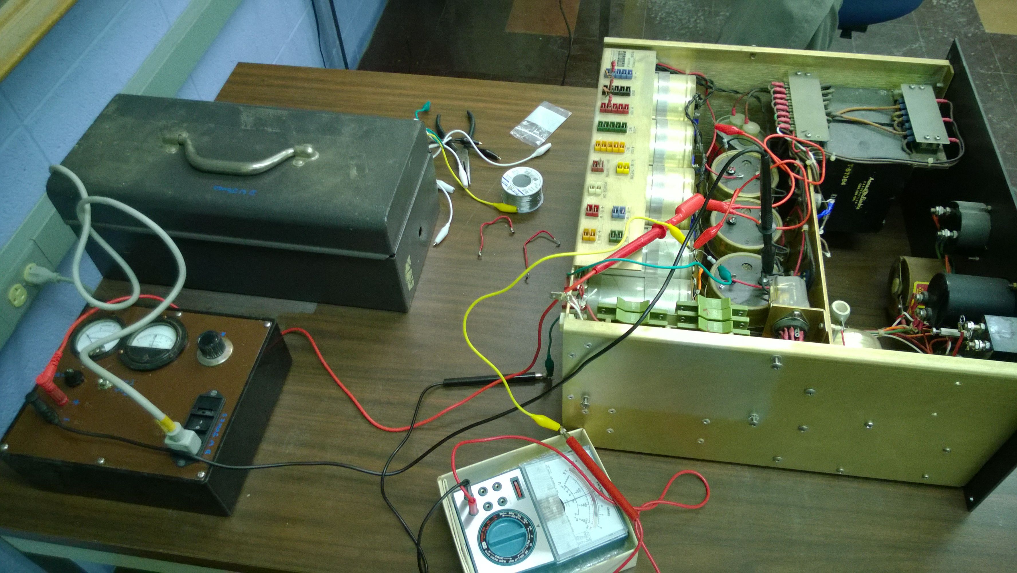
10V at 10A 300mV
|
|

|
|
|
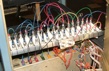
With the capacitors reformed and the power supply reassembled, it is time
to test it. This involves constructing a dummy load and measuring all of
the outputs under this load.
Bug 34: Reverse engineer the Tally reader interface
Type 750C controller, as found
|
|
|
|
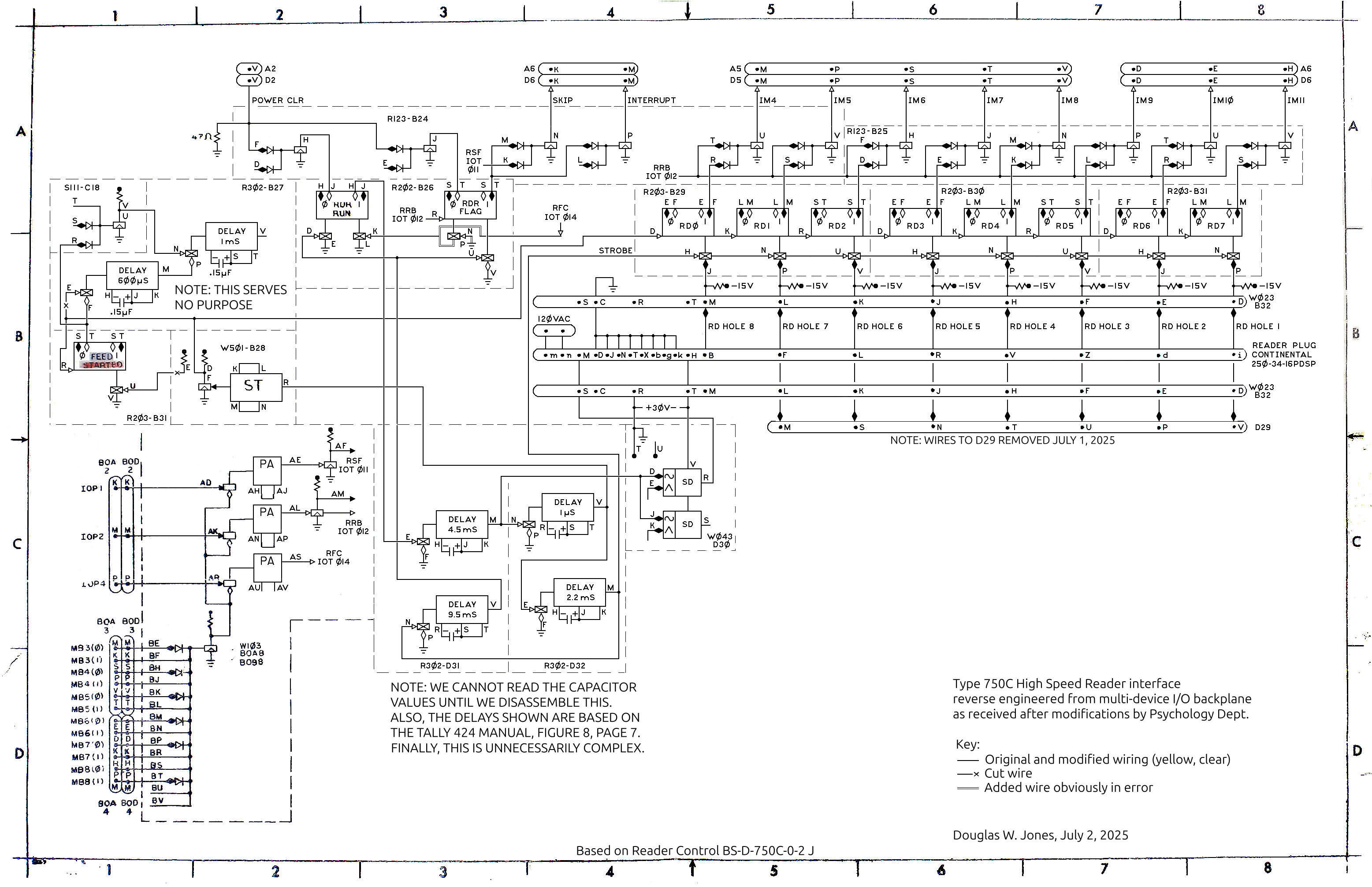
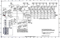
The
Tally 424
paper tape reader interface is a subsystem of the
Type 34D Oscilloscope Display backplane.
DEC designed this interface as the
Type 750C
High Speed Reader, but that
interface appears to be designed for a photoelectric reader. There is
evidence of tinkering in the backplane here, so we need to thoroughly
understand what was done to make the DEC interface work with the Tally reader.
- created, June 2, 2014.
- Progress, June 13, 2014.
Cable connector reverse engineered.
- Progress, Oct. 2, 2014.
Backplane reverse engineering started.
- Reopened, June 24, 2025.
- Major progress, July 1, 2025
Controller, as found, reverse engineered.
- Progress, Feb. 3, 2026
Timing diagram for Tally 424 reader.
- Solved?, Mar. 5, 2026
Annotated schematic from July 1, 2025.
Bug 35: Fix Marginal Check supply panel meter
Trimmer added
|
|
|
|
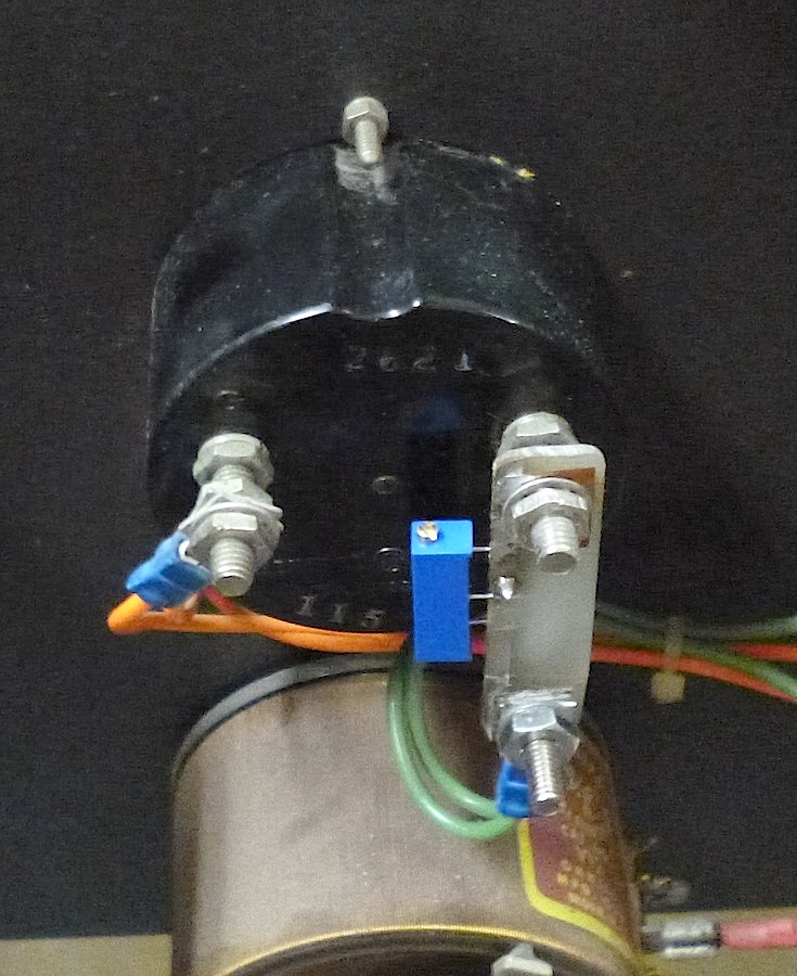
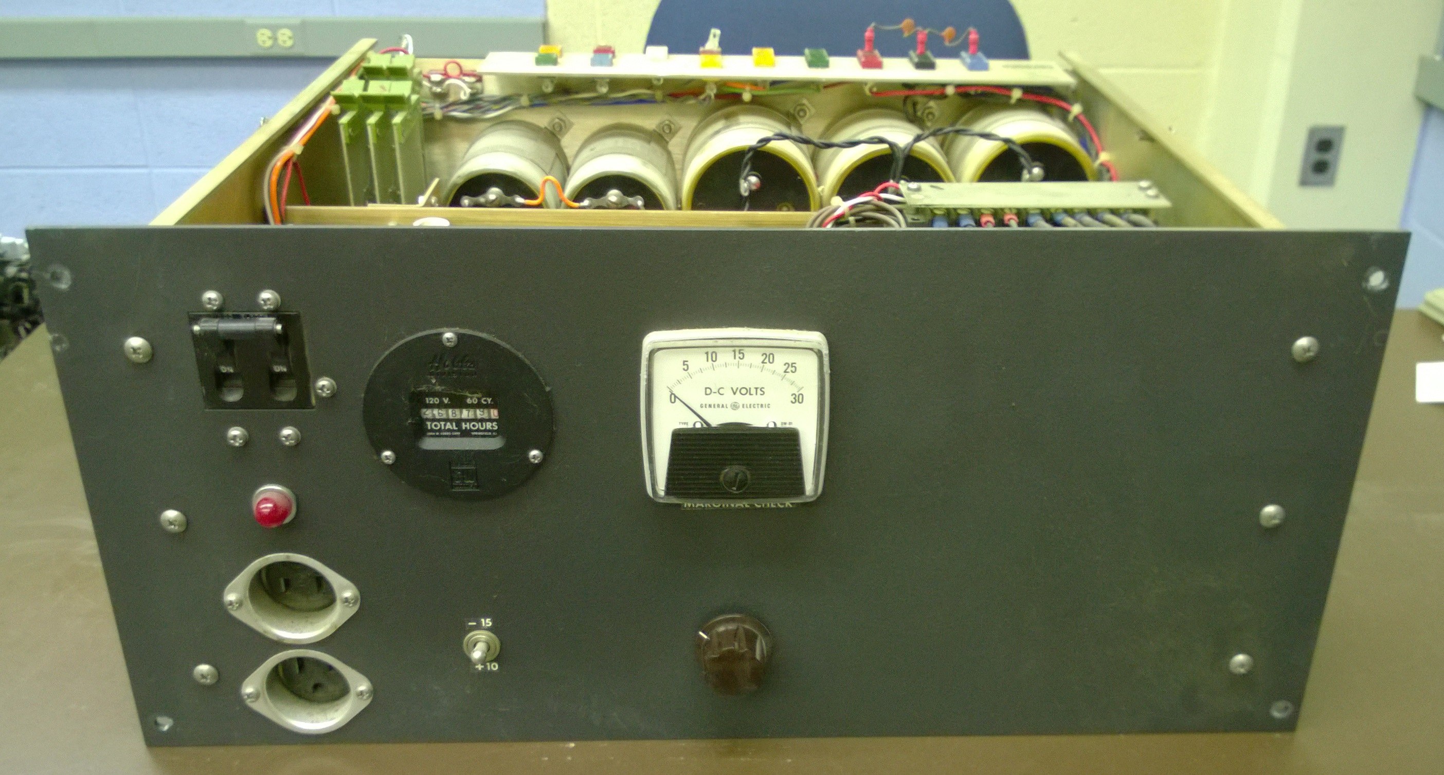
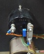
The Marginal Check power supply panel meter reads about 10% high compared
to the VOM used in power supply testing.
Bug 36: Fix the Inhibit and Read/Write supplies
The Inhibit and Read/Write supplies do not work. These are regulated
supplies with outputs that only connect when both voltages are within spec.
A relay driver performs the logical and function.
- created, Aug. 13, 2014.
Created Bug 37.
- Progress, Oct. 29, 2014.
Preliminary measurements.
- Progress, Nov. 12, 2014.
Dead-end hypothesis.
- Progress, Nov. 18, 2014.
Boards were in wrong slots!
- Solved?, Dec. 16, 2014.
Outputs within spec.
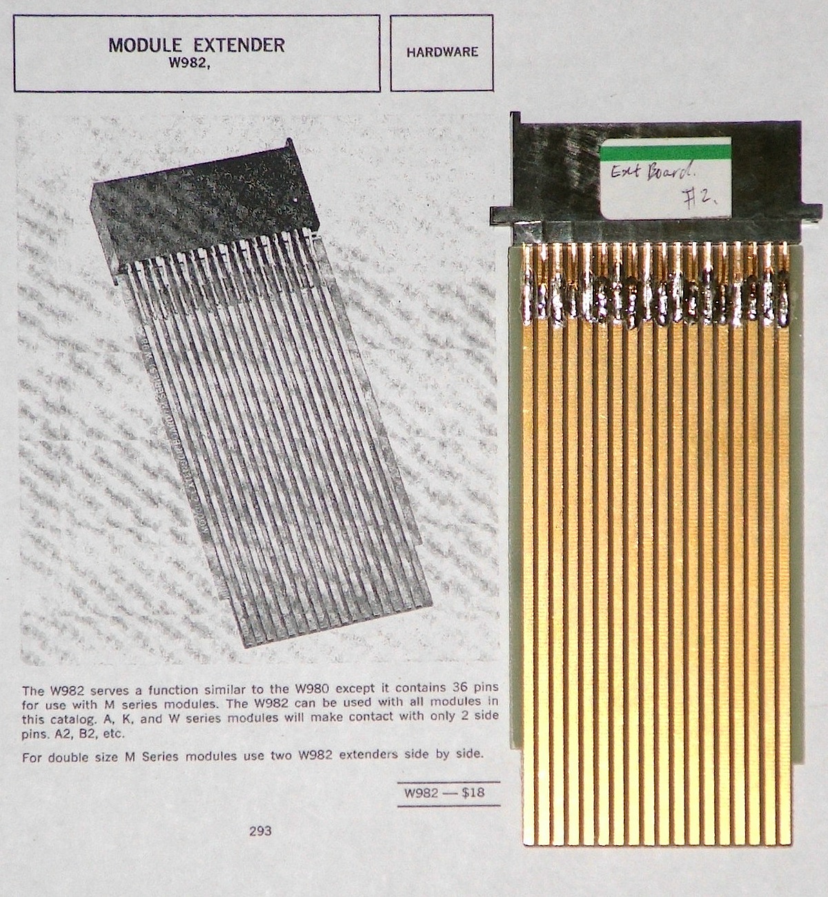
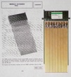
Bug 37: Get or build Flip-Chip Module Extenders
W982 board
|
|
|
|
The Inhibit and Read/Write supplies do not work. These are regulated
supplies with outputs that only connect when both voltages are within spec.
A relay driver performs the logical and function.
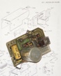
Bug 38: Repair and mount Teletype tape-reader supply
The supply
|
|
|
|
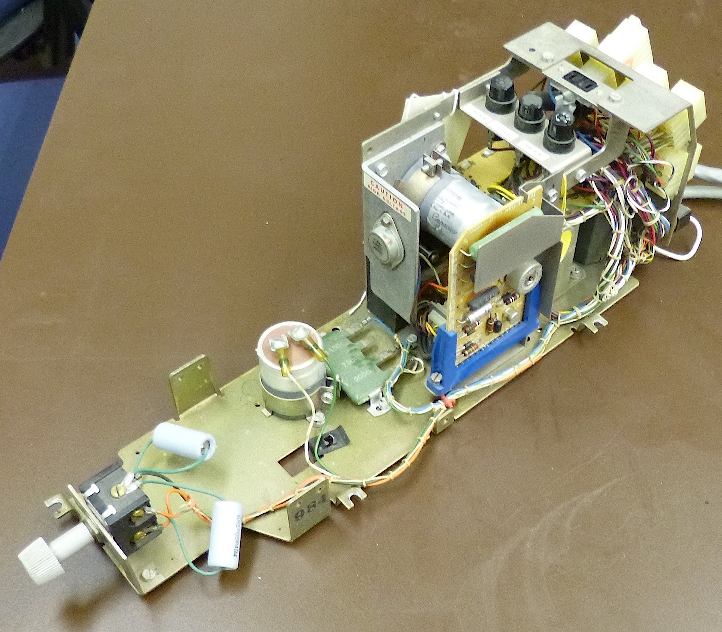
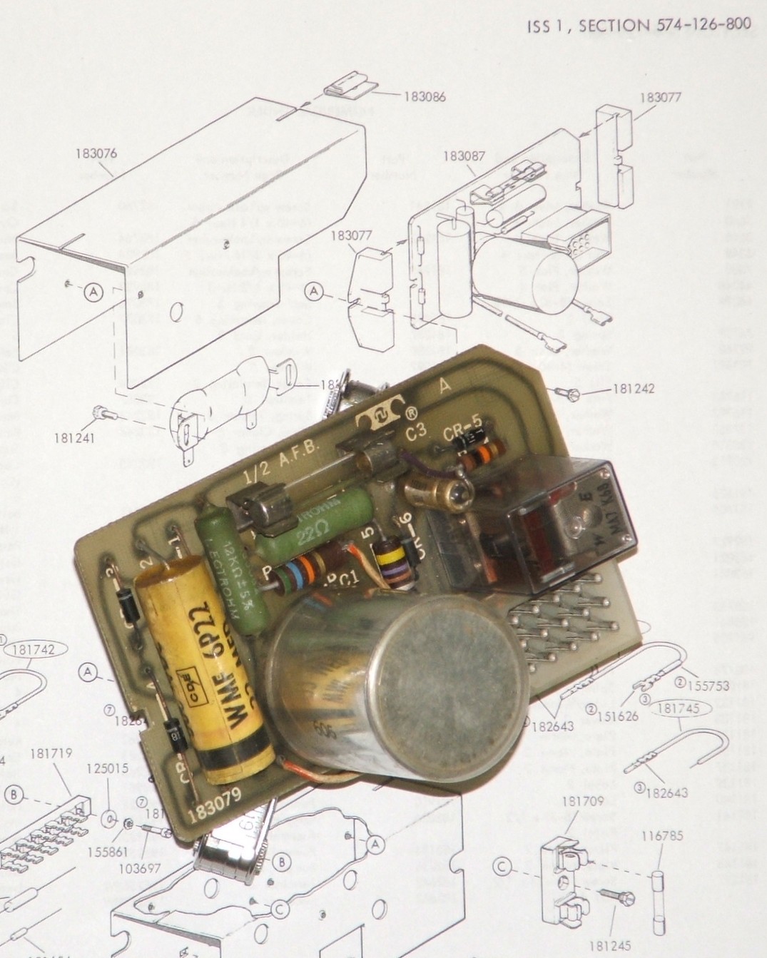
The power supply for the Teletype mounts either on the Call Control Unit
or on in the Teletype pedestal. Our supply was missing, but we obtained a
broken one from eBay for a pittance. Unfortunately, it is broken, and it
came without a mounting bracket.
- created, Sep. 9, 2014.
Broken power supply obtained.
- Progress, Sept. 10, 2014.
Missing circuit trace rewired.
- Progress, Nov. 9, 2014.
- Progress, Nov. 11, 2014.
Mounting bracket fabricated and installed.
- Progress, Nov. 14, 2014.
Fish paper and grounding strap installed.
- Solved, Dec. 1, 2014.
Fish-paper shield installed. Now, we need to reform the
capacitor, more work on Bug 10.
Bug 39: Repair or replace broken Teletype screw
Old and new screws
|
|

|
|
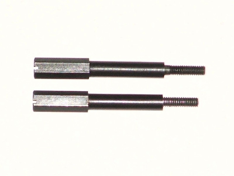
Teletype part-number 182891 is a very unusual screw. Unfortunately,
the fat screw head invites overtightening. Fortunately, the huge
screw head means that this screw can be repaired.
- Created Nov. 11, 2014.
Overtightened screw breaks.
- Solved, Dec. 1, 2014.
Old screw head drilled and tapped to hold a new screw body.
Bug 40: Repair G007 sense amplifier
The broken board
|
|

|
|
|
The repair
|
|

|
|
|
The sense amplifier in backplane slot MB30 was damaged during the
backplane inventory and cleaning (see
Bug 19). The repair was essentially straightforward.
- noted, Dec. 4, 2014.
Broken pin-connector socket for sense wire on handle-side of board.
- Solved, Dec. 5, 2014.
Repaired using D-subminiature socket parts.
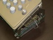
Bug 41: Repair Teletype keyboard cover
Lugs replaced with screws
|
|
|
|
The cover over the Teletype keyboard was supported and aligned on 3 mounting
lugs, all of which have broken off.
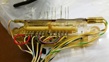
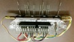
Bug 42: Rebuild Teletype keyboard contact block
Original
|
|
|
|
|
Rebuilt
|
|
|
|
|
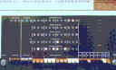
Bug 43: Test PDP-8
With the power supply tested and the rack wiring fixed, we can
turn on the computer. Now we must see if it works!
- noted, Feb. 04, 2015.
First power to PDP-8, some front panel lights work.
- Stalled Feb. 05, 2015.
Created Bug 44.
- Stalled Feb. 11, 2015.
Created Bug 46 and Bug 47.
- Progress, Apr. 21, 2015.
Begun functional testing from the front panel;
found some bugs.
- Progress, Apr. 22, 2015.
Created Bug 49, also note some poor switches.
Running a test
|
|
|
|
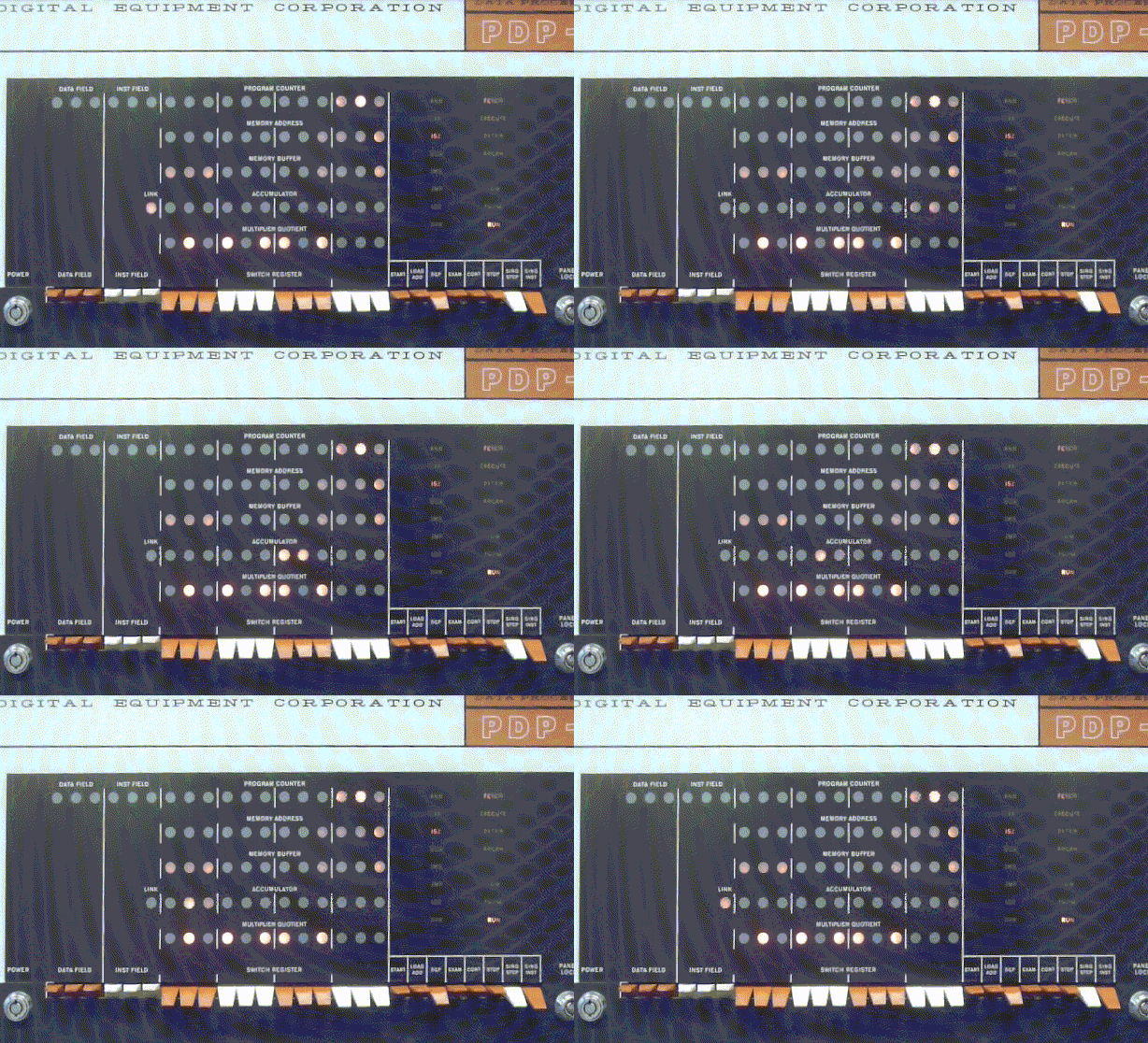
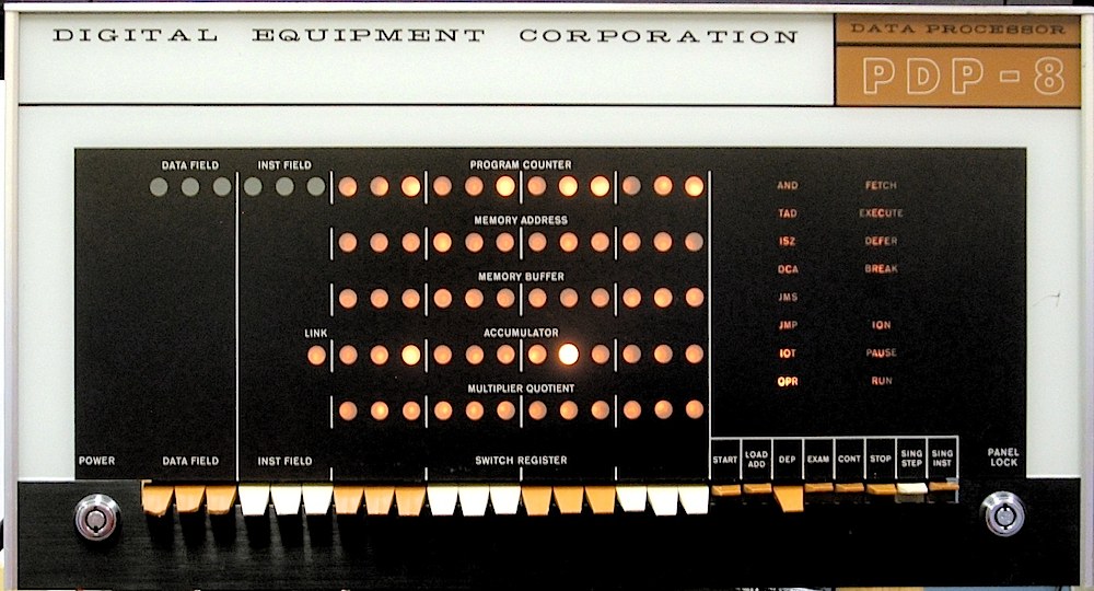
- Major progress, July 10, 2025
Start programming!
- Progress, July 15, 2025
More programming.
- Progress, July 15, 2025
Video of front panel.
- Progress, July 22, 2025
Video of testing MQ register.
- work, Sep. 29, 2025
First attempt to use TTY interface.
- Progress, Oct 6, 2025
TTY interface does not work.
Created Bug 77.
- Progress, Oct 9, 2025
TTY output works.
- Progress, Oct 16, 2025
TTY input works.
- Progress, Oct 30, 2025
Subroutines work.
- Progress, Feb. 19, 2026
Bigger TTY demo works, trouble with BIN loader.
- Progress, Mar. 24, 2026
JMS instruction tested.
- Progress, Apr. 21, 2026
ODT ODT debugger loads and runs, but something is wrong.
- Progress, Apr. 23, 2026
Diagnostic for autoincrement addressing runs.
- Progress, Apr. 28, 2026
Diagnostic for RTR fails, creating Bug 86.
- Progress, May 7, 2026
Successfully use ODT to examine, patch and run some code.
- Progress, July 17, 2026.
Start testing I/O bus.
- Progress, July 21, 2026.
All IOTs to device 01 seem to work.
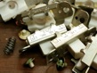
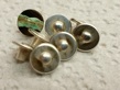
Bug 44: Repair PDP-8 marginal check switches
Switch parts during cleaning
|
|
|
|
|
|
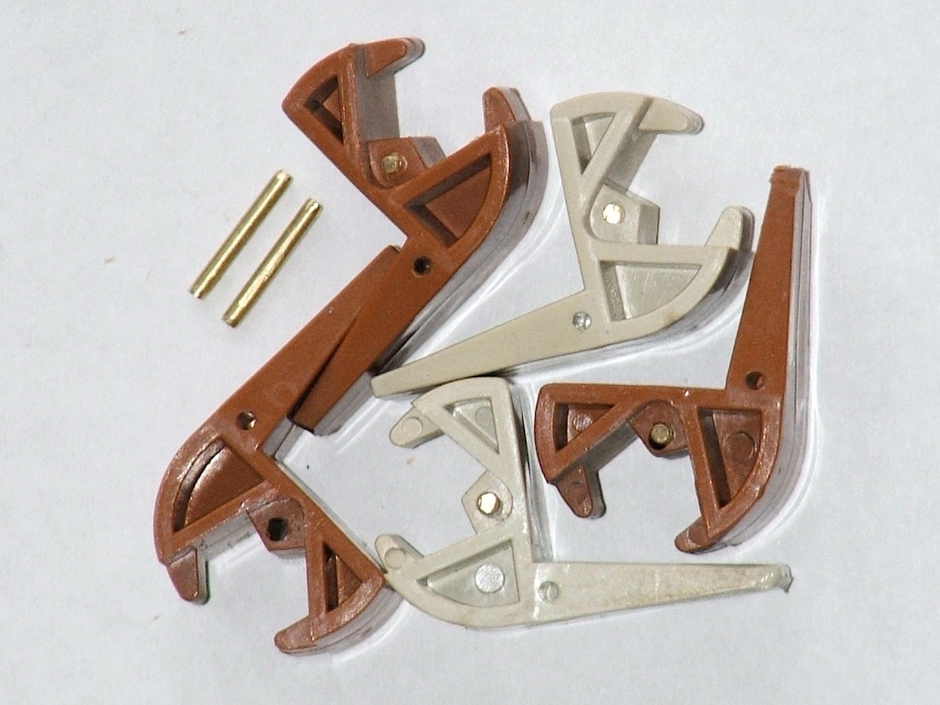
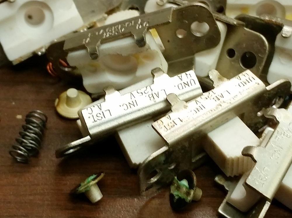
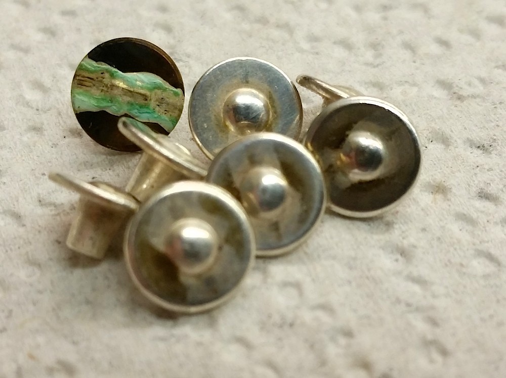
After turning on the computer, we found that power was not reaching
all parts of the PDP-8 backplane. The problem turned out to lie in the
switches that allow switching each row of the backplane from the primary
power supply to the variable voltage marginal-test power supply.
Repair or replacement of these switches is in order.
- noted, Feb. 05, 2015.
Document the switches.
- Progress, Feb. 06, 2015.
Begin repairing the memory-side switches.
- Progress, Feb. 09, 2015.
Finish memory-side switches, start CPU-side.
- Progress, Feb. 09, 2015.
- Solved, Feb. 10, 2015.
All switches reassembled and power wiring tested.
Bug 45: Clean PDP-8 backplane fans
Cleaning the fans
|
|
|
|
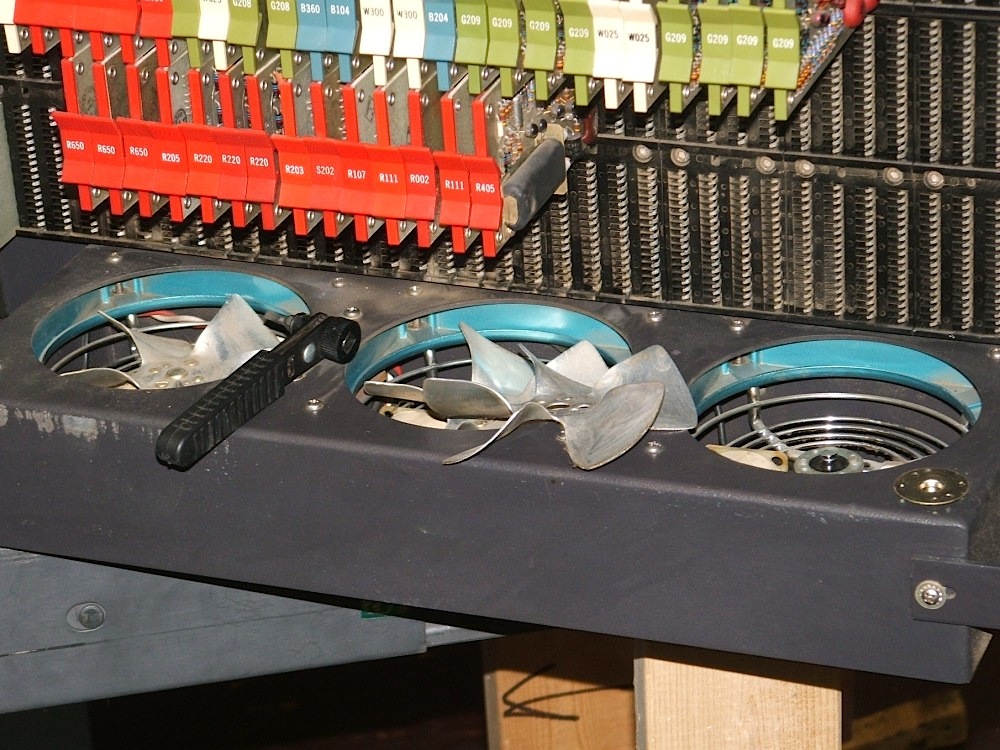
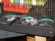
There was considerable dust on the bottoms of the 3 fans at the bottom of
each half backplane of the PDP-8, so we removed the fan blades from their
motors, cleaned everything, and then opened the motor hubs and oiled them.
Bug 46: Reassemble PDP-8 front panel
The front panel removed
|
|
|
|
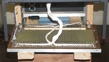
To deal with Bug 1 and Bug 47,
we had to disassemble the PDP-8 front panel. It will need reassembly.
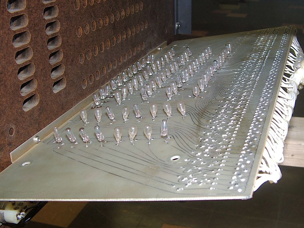
Bug 47: Fix burnt-out front panel bulbs
The lamps
|
|
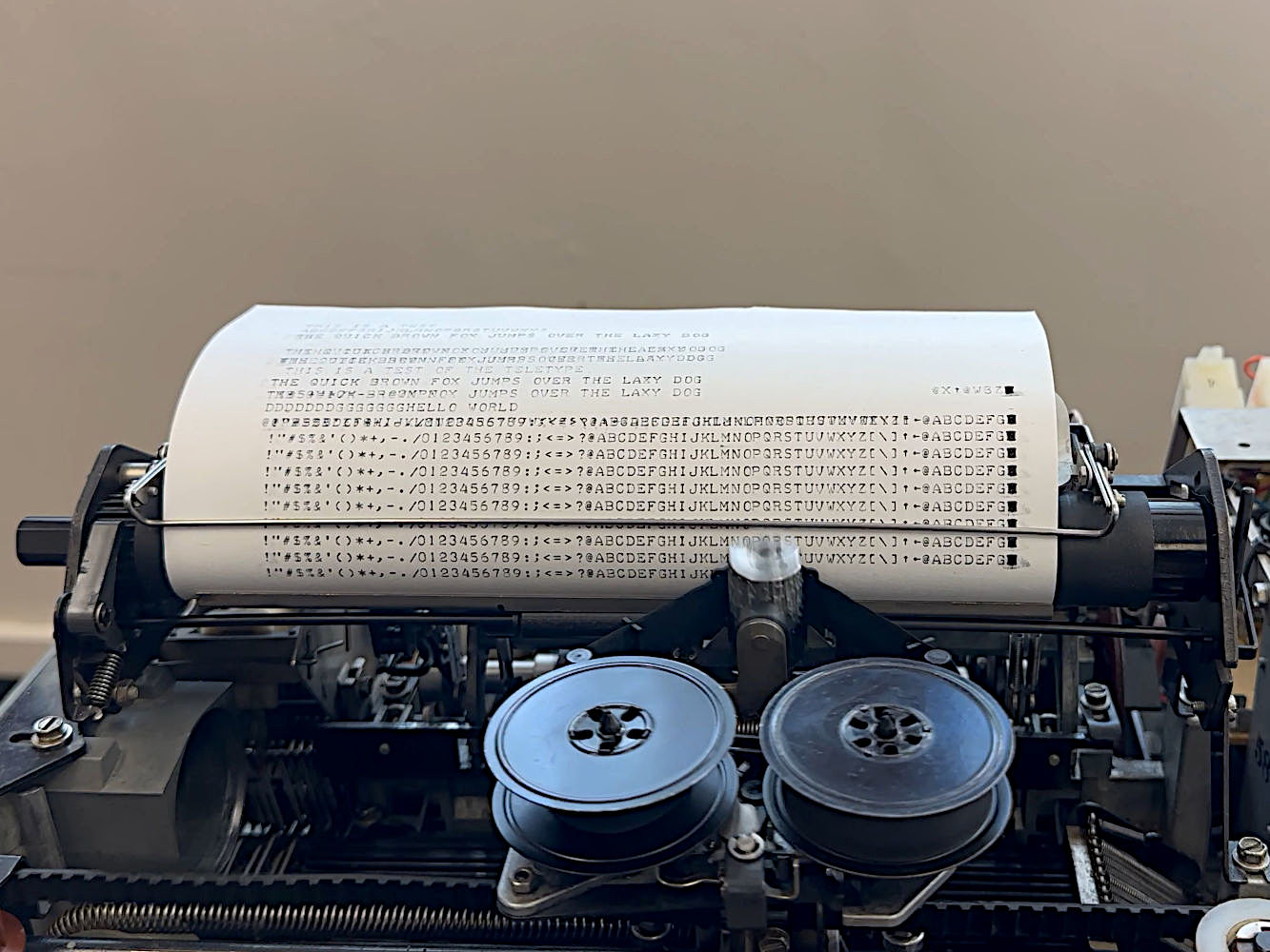
|
|
|
All lamps lit
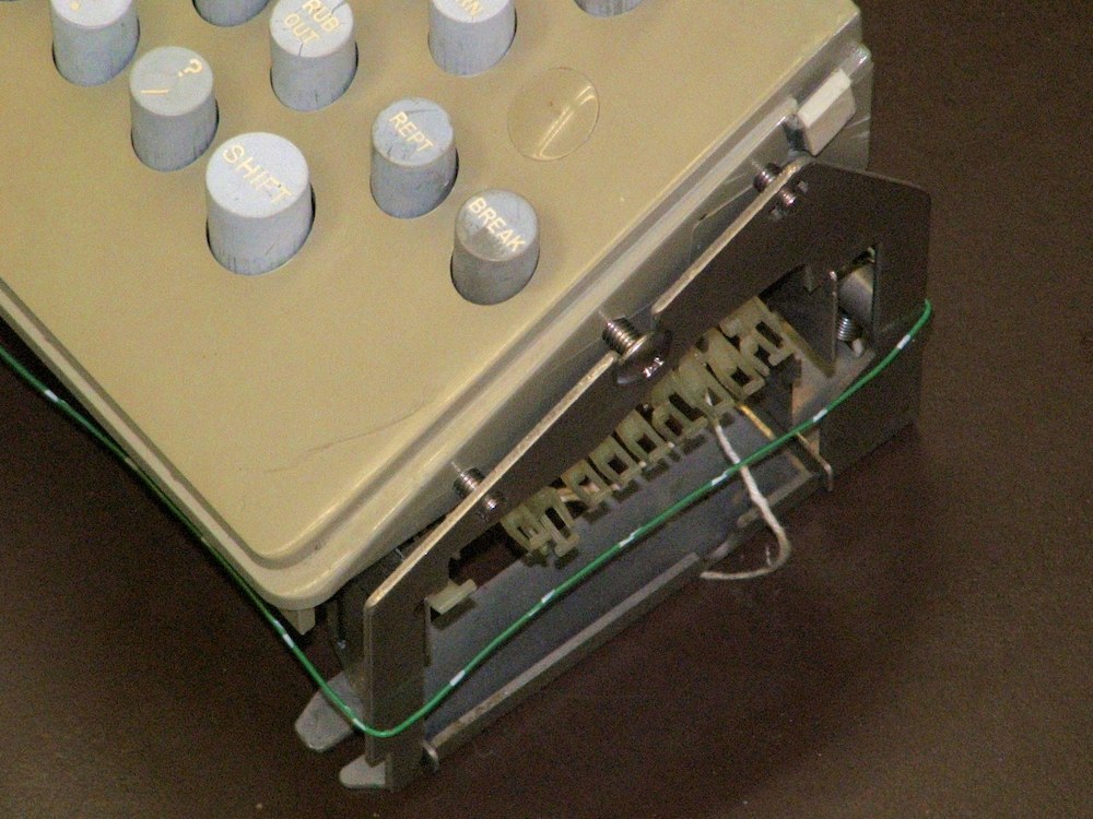
|
|
|
|
|
When we began testing the PDP-8
(Bug 43)
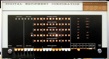
we found that many of the bulbs on the
front panel did not light, although other evidence suggested that
the bulbs ought to light.
- created, Feb. 11, 2015.
Front panel removed and opened up.
- Progress, Feb. 17, 2015.
Got replacement lamps and reverse engineered lamp circuitry.
- Progress, Feb. 23, 2015.
Replaced a total of 28 lamps, one remains inoperable, a bad transistor?
- Progress, Apr. 3, 2015.
Open up front panel to gain access to transistor in question.
- Progress, Apr. 6, 2015.
The problem was a bad circuit trace, not a bad transistor.
- Progress, Apr. 9, 2015.
Three more lamps failed during front panel reassembly.
- Solved, Apr. 13, 2015.
All lamps now light!
Bug 48: Test Teletype
First test
|
|
|
|
|
11 weeks later
|
|
|
|
|
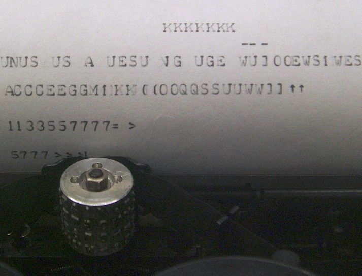
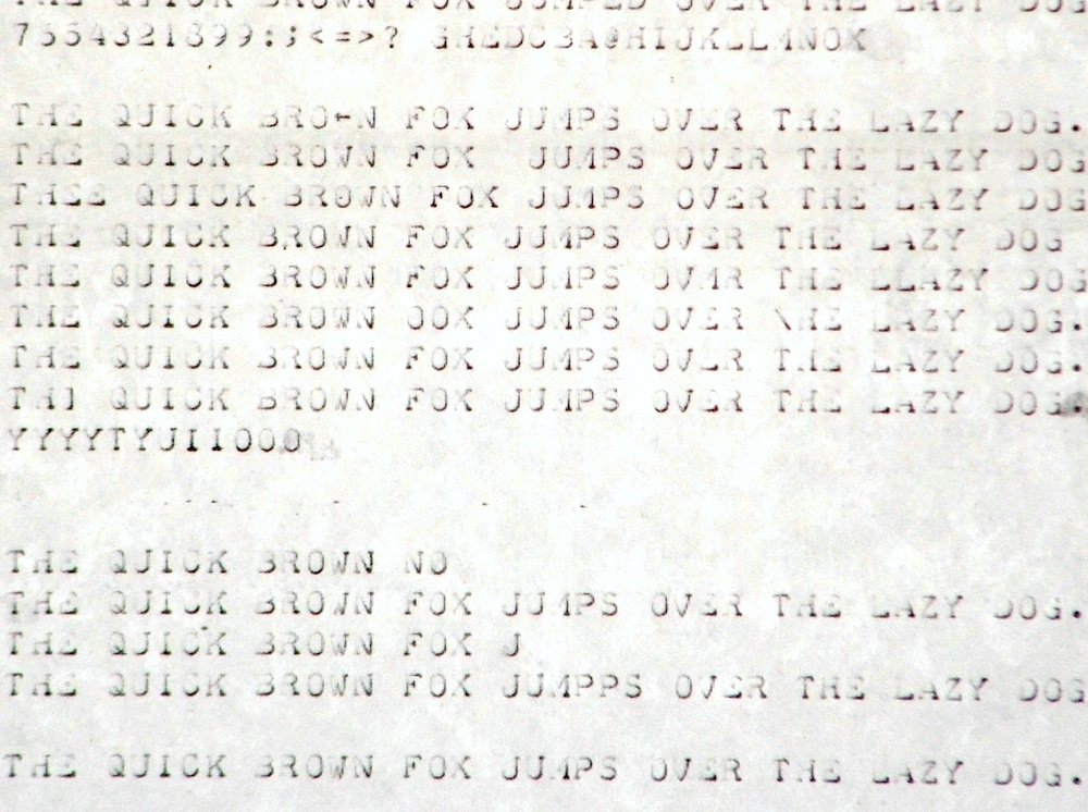
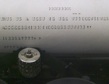
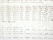
Having reassembled the Teletype, it is time to see how it works.
- created, Feb. 16, 2015;
it chatters away when it should be idling.
- Progress, Oct. 14, 2015;
Created Bug 52, adjust the Teletype.
- Progress, July 19, 2016;
Tape punch works but punches wrong data.
- Progress, July 20, 2016;
Tape punch works, punches as typed.
- Progress, Sep. 13, 2016;
Space, CR, LF, work, but types wrong letters.
- Progress, Sep. 27, 2016;
Most letters print most of the time, but stutters.
- Progress, Oct. 13, 2016;
M misprints as ←, and F, N, V and 6 misaligned.
- Progress, Dec. 1, 2016;
S occasionally misprints as ←, T and I also problematic.
- Progress, Dec. 8, 2016;
Pretty reliable, but occasional doubles and the bell rings too much.
- Progress, Mar. 7, 2017;
Very reliable, but occasional problems with V and W at high speed.
Bug 49: Repair R211 board
Testing the R211
|
|
|
|
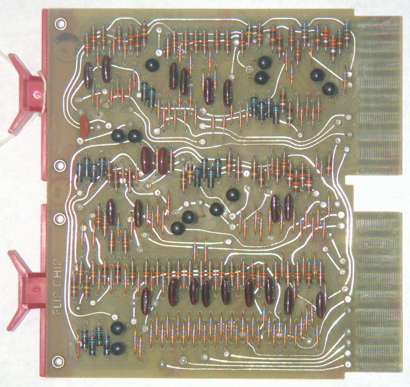
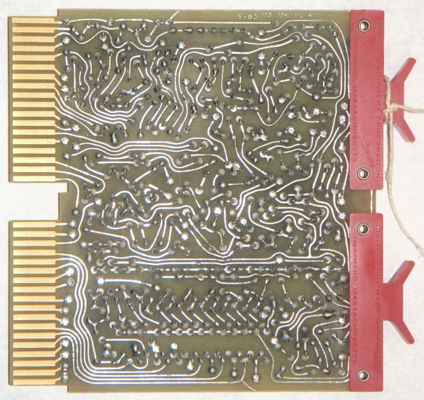
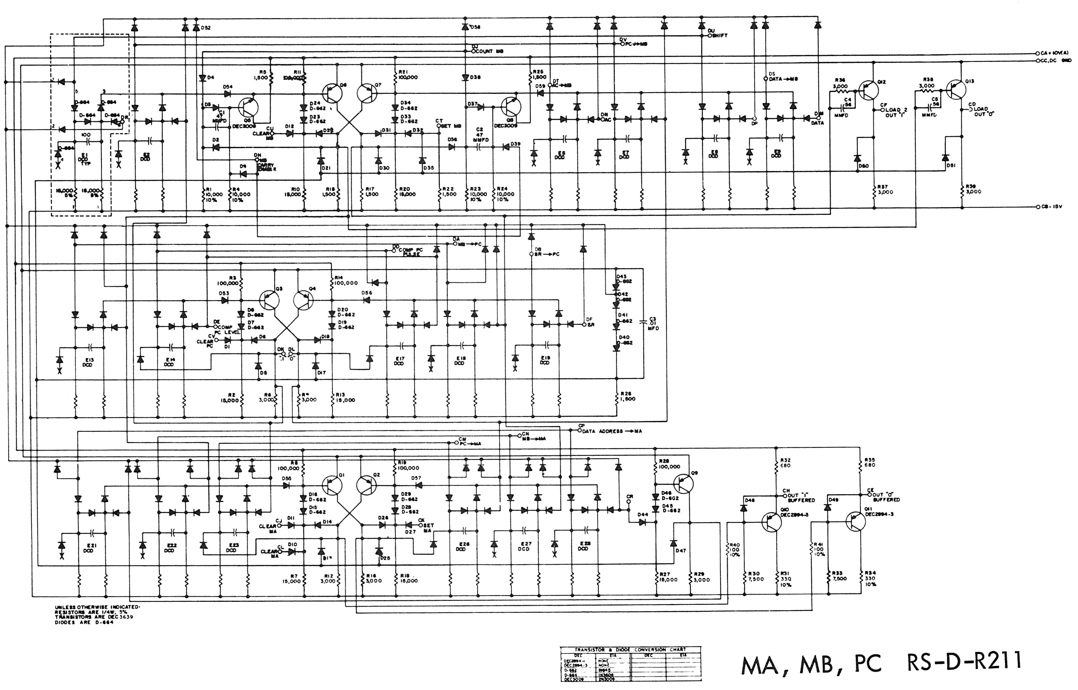
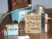
The R211 boards are double-height boards.
Each hold one bit of the memory address, program counter
and memory data registers, plus the multiplexer logic for
loading those registers.
- created, Apr. 22, 2015;
The MA register on the board in slots PC8 and PD8 seems to be stuck on.
- Progress, May 19, 2015;
Something got hot when the board was powered up.
created, Bug 51.
- Progress, May 22, 2015;
took board photos,
creating Bug 50.
- Progress, June 8, 2015;
discovered that tests on May 19 may have damaged board.
- Progress, June 24, 2015;
tests on May 19 appear to have done no harm.
- Progress, July 2, 2015;
board testing points to bad transistor.
- Progress, Sept. 30, 2015;
the problem was a bad diode.
- Problem reopened Apr. 6, 2017;
PC carry propagation problem observed,
see Bug 61.
- Progress, Apr. 20, 2017;
Bad diode found, but a different bit will not load from switches.
Bug 50: Reverse engineer the R211 board
The R211 H board
|
|
|
|
|
|
|
Reverse engineered
|
|
|
|
|
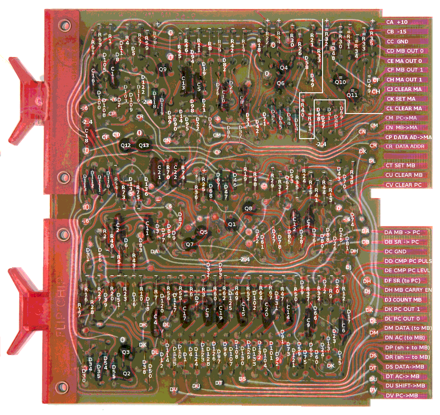
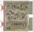
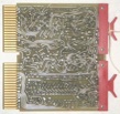
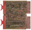
The R211 boards are extraordinarily complex double-height boards, where
relating components on the board to the schematic diagram is not easy.
The image showing the result of the reverse engineering shows both sides
of the board, superimposed (with traces on the solder-side shaded red).
The text gives part numbers; those prefixed with equals signs (=) reference the
1965 schematic
of the R211 H;
those without reference the
1966 schematic
of the R211 J.
Markings on vias relate them to pins on the card edge connector or to the
voltages distributed on that circuit trace.
Bug 51: Build Flip-Chip board test rig
Test fixture
|
|
|
|
|
Logic probes
|
|
|
|
|
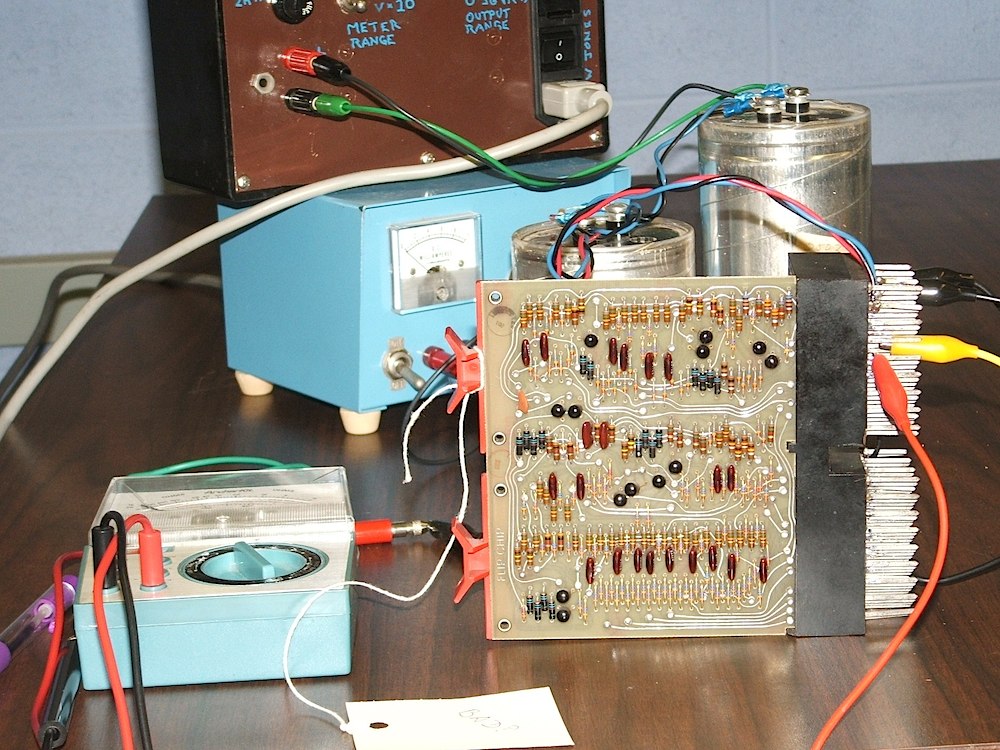
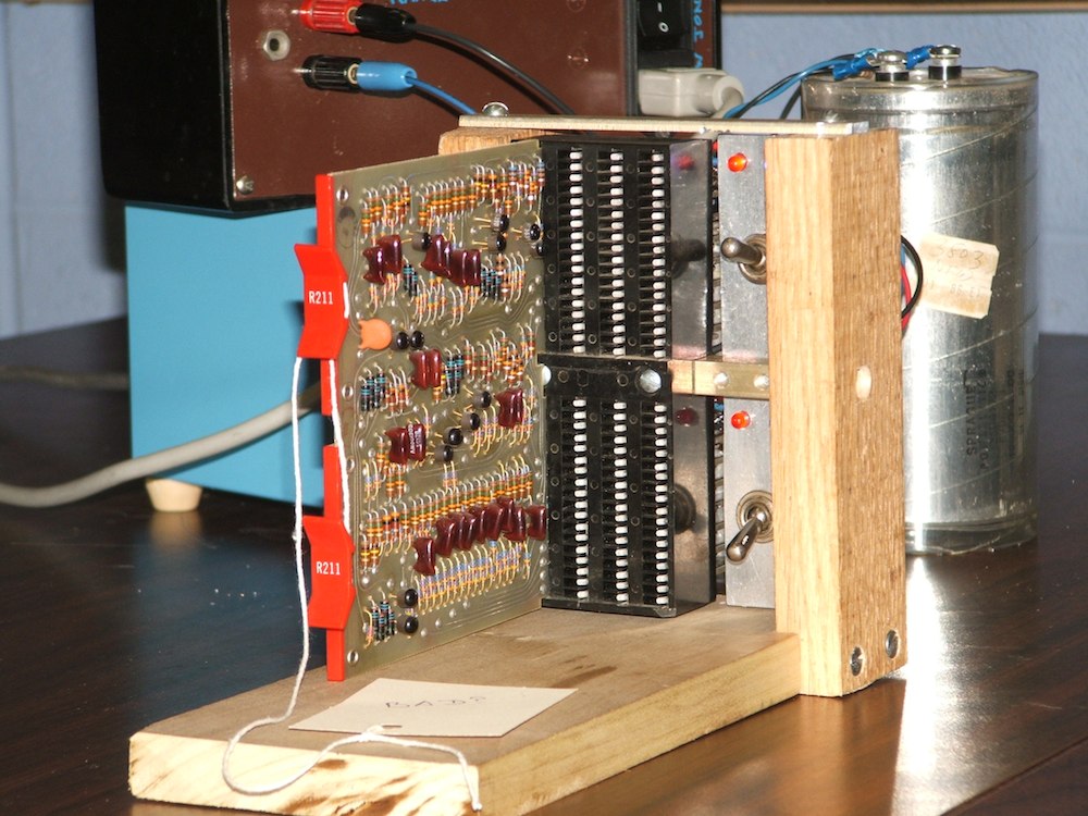
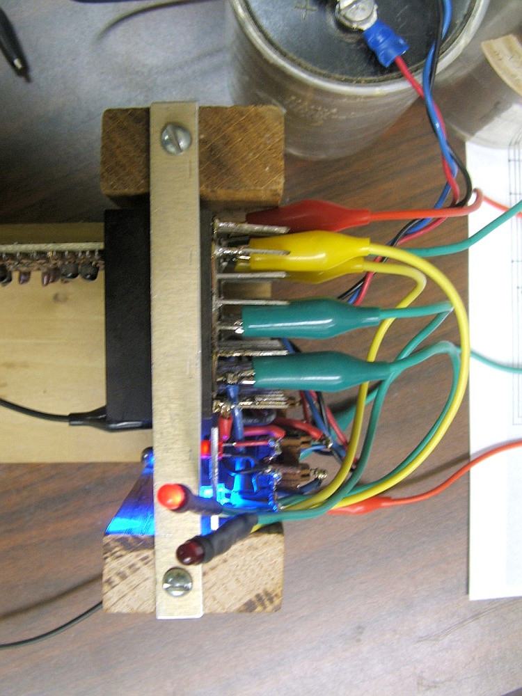
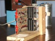
Testing boards from the PDP-8 is easier if they can be tested outside
the PDP-8 backplane. This required building a test rig and a logic test
probe.
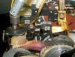
Bug 52: Adjust the Teletype
Reader stop latch
|
|
|
|
|
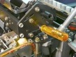
Platten height
|
|
|
|
|
There are numerous adjustments that must be made after disassembling and
reassembling the Teletype.
- created, Oct 14, 2015;
adjusted universal lever and reader stop latch.
- Progress, July 19, 2016;
can type to punch and typing unit, results are frequently wrong.
- Progress, July 20, 2016;
"rangefinder" adjusted, punch reliably outputs what is typed.
- Progress, Sep. 27, 2016;
Correctly types most of the time, but stutters.
- Progress, Oct. 13, 2016;
Fixed stutter in function clutch (release needed adjusting).
- Progress, Nov. 15, 2016;
Fixed tension on selector magnet armature.
- Progress, Dec. 1, 2016;
Adjusted selector armature, rear carriage rail height.
- Progress, Dec. 8, 2016;
Selector armature, print hammer trip lever, distributor trip linkage.
- Progress, Feb. 2, 2017;
Adjust paper-tape punch penetration.
- Progress, June. 22, 2017;
Adjust platen height and type-drum centering.
- Progress, June. 29, 2017;
Adjust line feed drive link and up stop.
- Progress, June. 25, 2017;
Adjust platen height again.
- noted, Oct 13, 2025;
Teletype keyboard data has glitch.
- Progress! Oct 16, 2025;
Software can echo keyboard input to printer!
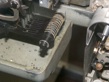
Bug 53: Missing felt washers in Teletype punch
Felt washers
|
|
|
|
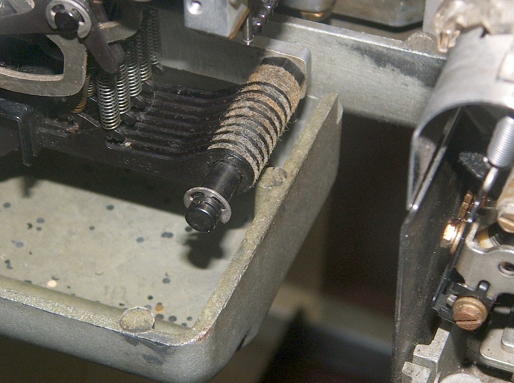
The outboard end of one of the pivot shafts in the Teletype is missing several
felt washers.
- created, Feb. 17, 2016;
made new felt washers, installation looks wrong.
Bug 54: Loose code bar bracket in Teletype
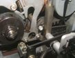
Code bar bracket
|
|
|
|
The bracket that serves as an alignment comb at the left end of the code bars
that serve as the main mechanical data bus in the teletype was not attached.
Floating loose on the code bars, it did not seem to be doing any harm, but
it should be attached.
Bug 55: Broken Teletype carriage-return lobe plate
Broken
|
|
|
|
|
Replaced
|
|
|
|
|
The carriage return lobe plate that mounts on the left side of the carriage
was broken. This prevents the spacing mechanism from working after a carriage
return because without it, the return lever stays latched, disengaging the
spacing pawls.
Bug 56: Teletype control-character linkage engagement
Most of the control-character actuating levers was not engaged properly
with the corresponding linkages, and the corresponding function levers were not
properly engaged with their function pawls.
- created, Aug. 12, 2016;
discovered the problem.
- Progress, Sep. 8, 2016;
CR function lever now decodes, but no actuation.
- Progress, Sep. 13, 2016;
CR seems to work correctly.
- Progress, Nov. 15, 2016;
BEL and ENQ seem to work correctly, but testing fails.
Bug 57: Teletype bell rings with every character
During reassembly of the Teletype, the automatic codebar was inserted in the
wrong slot in the codebar assembly, causing the function bell to ring with
every character typed.
Bug 58: Teletype bit 4 problem
After enough of the Teletype was repaired that the typing mechanism began
working reasonably reliably, there were misprints that focused on incorrect
values of data bit 4.
- First evidence Oct. 13, 2016;
Looking back through the logs, the evicence of this problem
was first recognized and connected to bit 4.
- created, Mar. 7, 2017;
Bit 4 only converted from 0 to 1 after a 1,
and the problem is in the receiver.
- Diagnosis Mar. 23, 2017;
The selector armature is being locked prematurely in the on position.
- Solved, Mar. 28, 2017;
A small rangefinder change fixes it!
Bug 59: Teletype platen needs reconditioning
The rubber of the teletype platen is very hard, limiting the print quality.
Is there some way to recondition it?
Bug 60: Teletype stand is missing its back
The back panel of the teletype stand is missing.
Can we manufacture a replica of the original?
Bug 61: Debug PDP-8 PC register
When you increment the PC, carry does not propagate from PC bit 2 to bit 1.
This is most obvious when you hit RUN with the memory disabled so all fetches
get opcode zero (AND). The PC lights up as
00X XXX XXX XXX, where bulbs marked X are on
at half intensity because they are flickering between 0 and 1.
- Problem diagnosed Apr. 6, 2017;
Moving boards pins the problem on an R211 board,
reopening Bug 49.
- Progress, Apr. 20, 2017;
Bad diode found, but a different bit will not load from switches.
Bug 62: Fix Teletype linefeed mechanism
Adjusting Height
|
|
|
|
|
Adjusting LF link
|
|

|
|
|
We broke the linefeed mechanism while adjusting the platen height.
- created, June 22, 2017;
We left a screwdriver in the left platen height
pry point when we hit LF.
- Solved, June 29, 2017;
Adjusting the line feed drive link and up stop compensated for
the bending or stretching caused by our error.
- Noted, Oct. 9, 2025;
Linefeeds only work when typed slowly.
- Solved, Feb. 24, 2026;
Tightened drive link, adjusted upstop.
Bug 63: Fix Teletype reader-run circuit
The problem spring
|
|
|
|
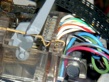
The paper-tape reader only runs if the clutch-trip magnet's armature at the
rear of the Teletype is held down manually. This is evidence that there's
something wrong in the wiring of the reader-run circuit.
- created, Mar. 7, 2017;
need to hold down clutch-trip armature discovered.
- Progress, July 6, 2017;
documents identified that show this should not be needed.
- Solved, July 11, 2017;
one contact spring in the reader was improperly reassembled.
Bug 64: Debug PDP-8 Memory
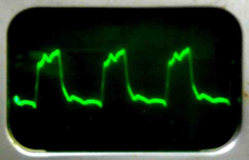
Inhibit and R/W select currents
|
|
|
|
|
|
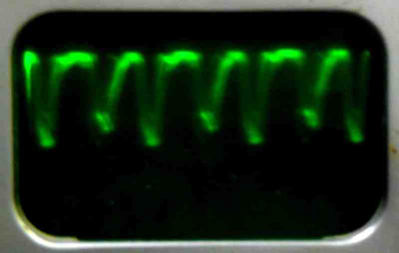
Memory does not work.
- Problem observed in passing Apr. 6, 2017;
memory does not work.
- Problem observed again Nov. 17, 2017;
can get data to MB register, but it reads back as zero.
- no progress Feb. 12, 2018;
speculate that a W034 cable is missing.
- small progress Feb. 21, 2018;
found the memory current limiters.
- small progress Apr. 4, 2018;
added test points to simplify current probe.
- Progress? Apr. 11, 2018;
preliminary current probe results.
- small progress Apr. 18, 2018;
useful current probe results.
- small progress Apr. 25, 2018;
check quality of power supply regulation.
- Progress? May 2, 2018;
swapping regulators has no effect.
- Progress? Sept. 13, 2018
Memory Strobe and Inhibit signals seem wrong.
- Progress? Sept. 27, 2018
Study B360 board that generates memory stribe.
- Progress? Nov. 8, 2018
Data tracked from the switch register to the Inhibit drivers.
- Progress? Dec. 6, 2018
Strobe pulse may be shorted to ground by a sense amplifier.
- Progress, Mar. 19, 2019
Reverse engineer G007 sense amplifier board.
- Progress? May 17, 2019
Replace open diode in G007 sense amplifier.
- verified status unchanged, Jan. 31, 2023
- found bug? Oct 9, 2024
Clock debugging.
- Progress, Oct 21, 2024
R603 reverse engineer and repair.
- Progress, Oct 28, 2024
Clock debugging.
- Progress! Oct 30, 2024
All memory timing waveforms verified to be correct.
- Progress! Nov. 4, 2024
Memory current settings measured, close to correct.
- Progress, Nov. 13, 2024
Memory current and voltage settings set by the book.
- Progress! Apr. 14, 2025
Memory starts to work!
- Progress! May 5, 2025
Sense amplifier outputs mostly good.
- Progress? May 30, 2025
Repair G208 inhibit driver.
- Workaround found, July 10, 2025
Work around problem, not repair it.
- noted, July 22, 2025
- Progress, Jan. 14, 2026
Explore range of slice voltages that work.
- Progress! Feb. 3, 2026.
Adjust voltages to make it work better!
- noted, Feb. 19, 2026
Is there a problem with odd numbered pages?
- progress, Mar. 31, 2026.
Problem with a G209 board in MD6 to MD9.
- progress, Apr. 7, 2026
Problem probably a G209 board numbered 9.
- Solved?, Apr. 16, 2026
Two cold solder joints fixed.
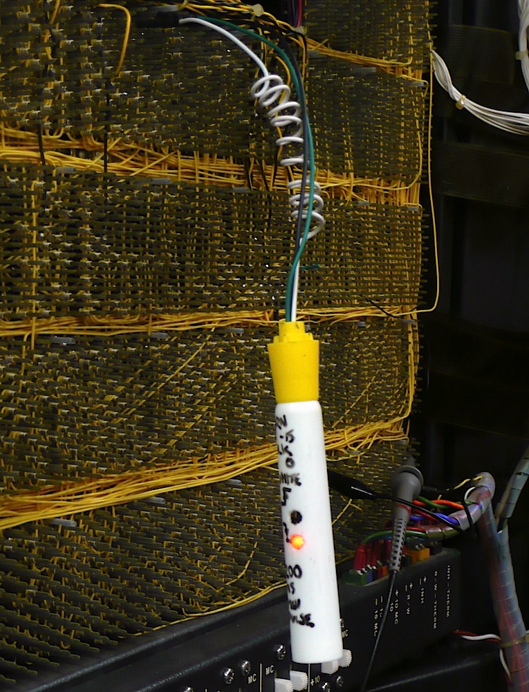
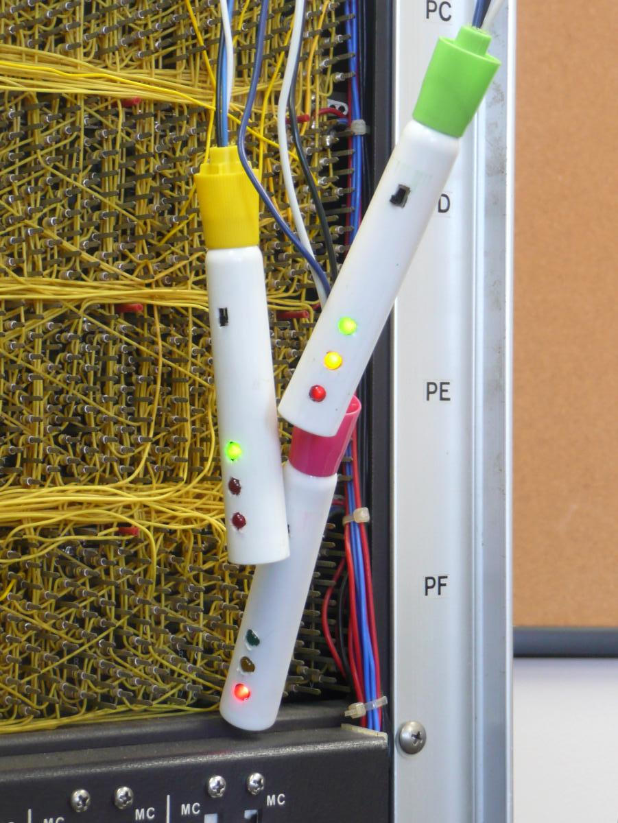
Bug 65: Built DEC R-series Logic Probes
First and second generation probes
|
|

|
|
|
|
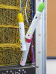
We found that we needed to watch signals on the wire-wrapped backplane, so
we built logic probes.
Bug 66: Fix marginal sense amplifier
Test fixture
|
|
|
|
We found that we could only achieve marginally acceptable static balance on
the G007 sense amplifier in slot MB27.
- Identify problem, Nov. 20, 2024
- Results of bug, Apr. 14, 2025
Cannot read bit 5 of memory!
- Progress, May 5, 2025
Sense amp seems to work, but no ones to read.
- Progress, May 8, 2025
Rule out a broken inhibit winding.
- Progress, June 5, 2025
Prove that the sense amplifier is bad.
- Progress, June 10, 2025
Diagnose G007 sense amplifier.
- Progress, July 3, 2025
Compare good and bad G007 boards.
- Progress, July 8, 2025
Balance and compare all G007's.
- Workaround found, July 10, 2025
- Progress, Oct 20, 2025
Replace Q2 on weak amplifier.
- Progress, Oct 23, 2025
Redo faulty measurements.
Bug 67: Eliminate noise on Memory Address
MA 11 and its inverse?
|
|
|
|
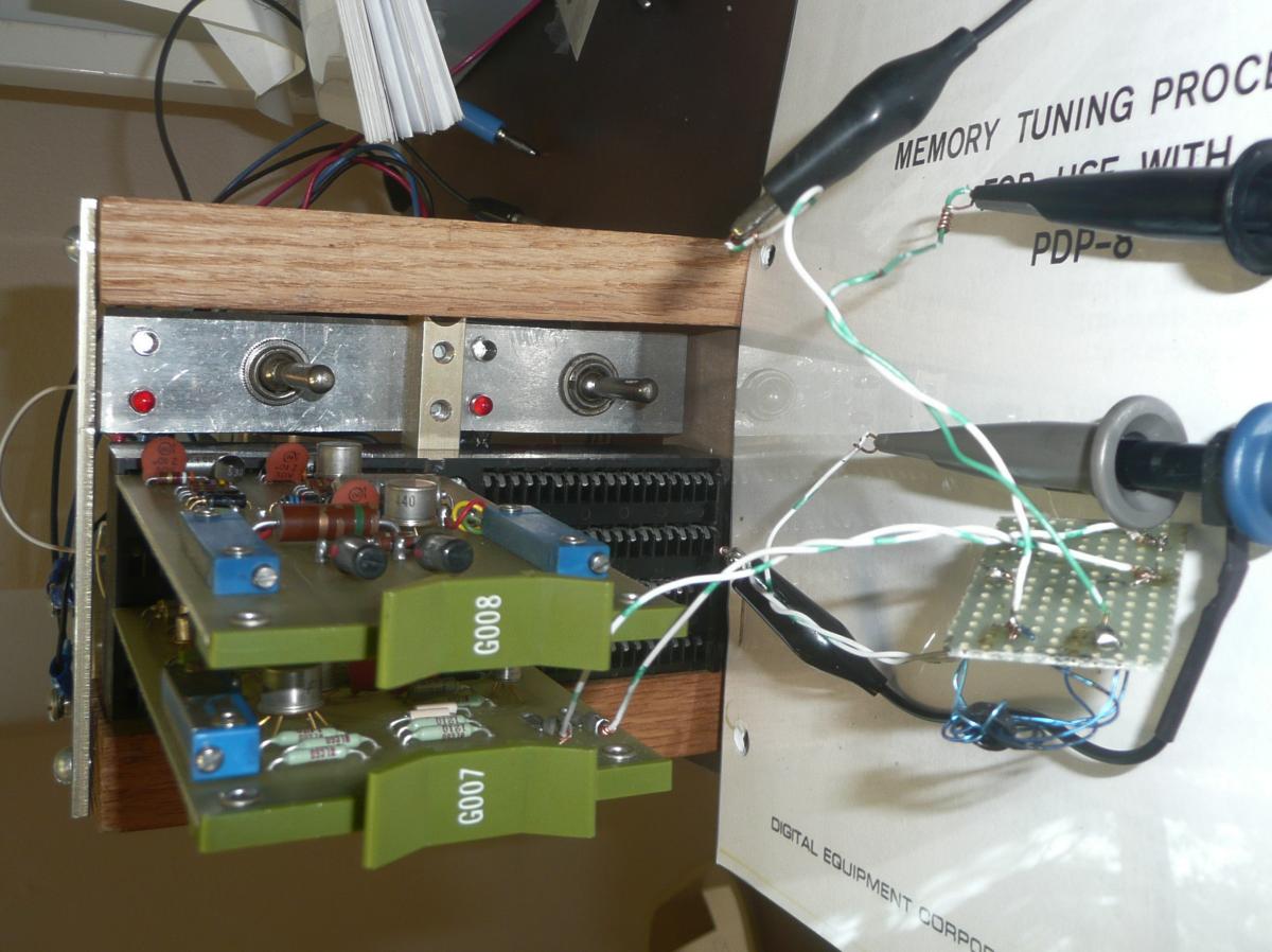
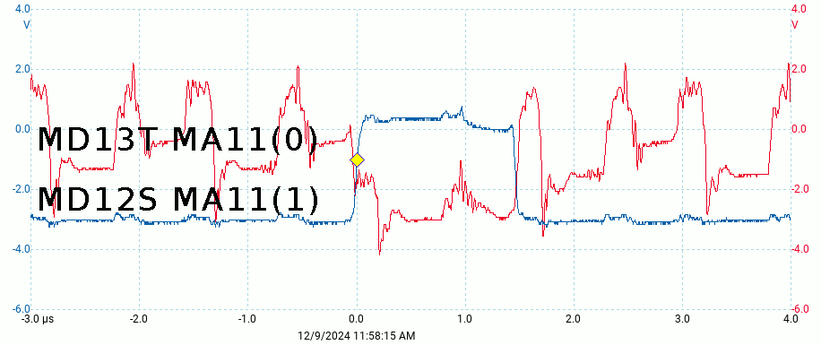
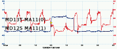
We found noise on one of the memory address line MA11(0) with an amplitude
exceeding the signal amplitude. We will have to check all the memory address
lines.
- Identify problem, Dec. 9, 2024
- Progress, Dec. 11, 2024
Identify G209s as noise source.
- Progress, Dec. 16, 2024
Repair diodes on G209 from slot MD12.
- Progress, Feb. 13, 2025
Repair diodes on second G209, others seem good.
- Solved?, Apr. 7, 2025
Test result of reapir.
- Solved?, Apr. 14, 2025
Memory starts to work!
- reopened, Apr. 7, 2026
Problem probably a G209 board numbered 9.
- Solved?, Apr. 16, 2026
Two cold solder joints fixed.
Bug 68: Fix burnt scope probe ground clips
New clips
|
|
|
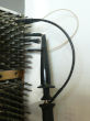
|
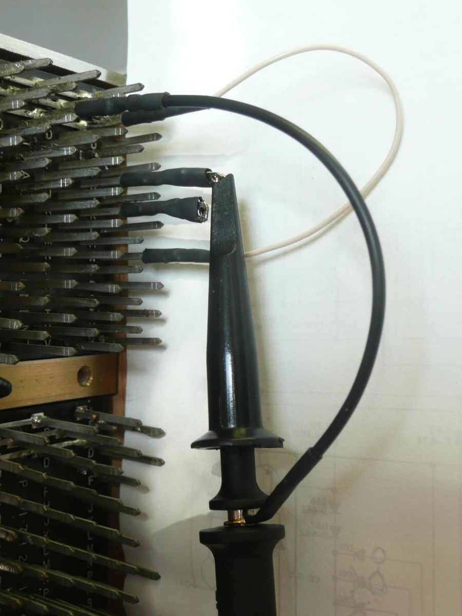
We managed to melt the wires in the ground clips of our scope probe by
shorting the +10 supply to ground through the scope. We also used the
technology we used to solve this problem to make push-on backplane
shorting jumpers.
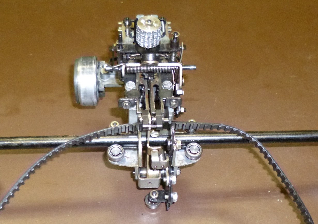
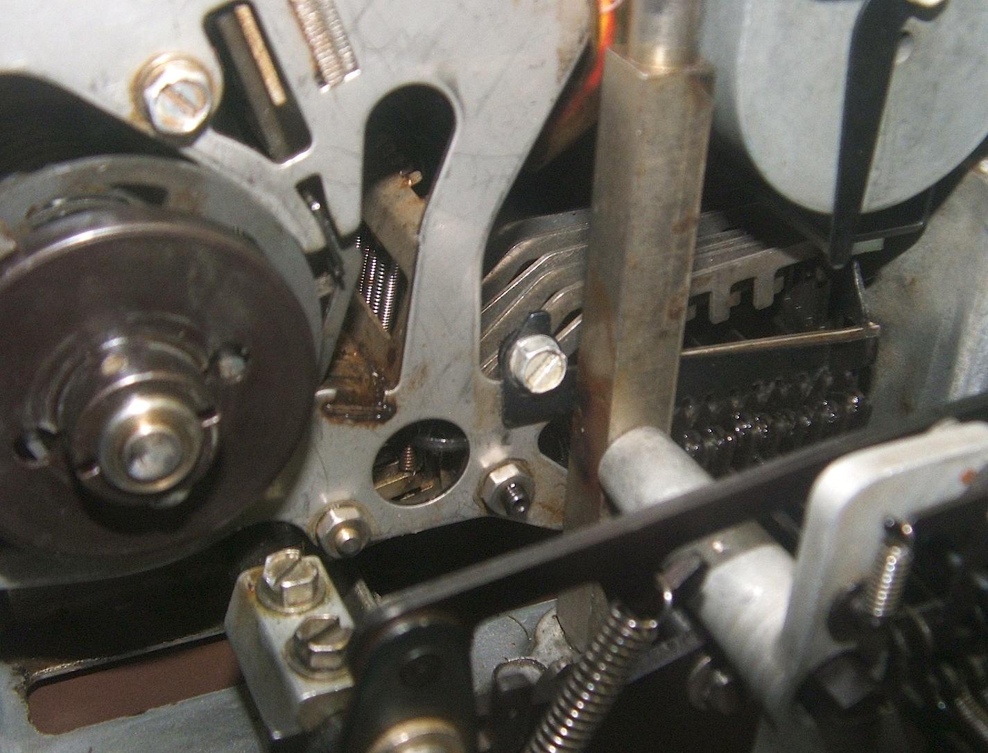
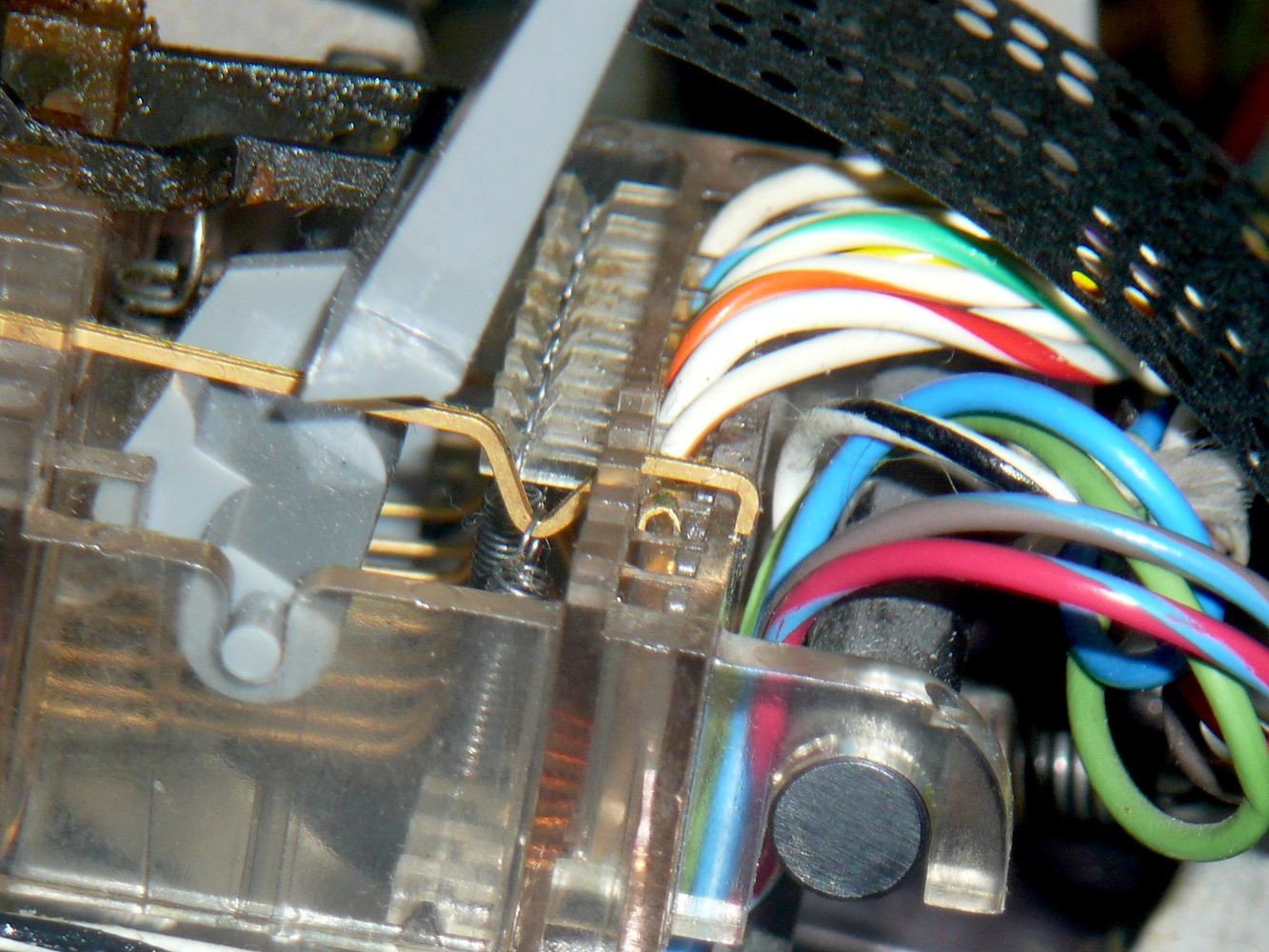
Bug 69: Combine 2 6-bit BRPE punches to get 8 bits
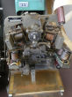
Parts donor
|
|
|
|
The PDP-8 documentation says it has an interface for an 8-bit BRPE paper-tape
punch. This was evidently modified by the psychology department to support a
different punch, which we do not have.
- Create problem, June 4, 2019
We got 2 6-bit BRPE punches.
creating Bug 71.
- Progress, Feb. 17, 2025
Start careful disassembly.
- Progress, Mar. 13, 2025
Extract linkages from one.
- Progress, Mar. 20, 2025
Reverse engineer punch block,
creating Bug 70.
- Progress, Mar. 31, 2025
Assemble BRPE linkages.
- Progress, Apr. 3, 2025
Reassemble widened BRPE.
- Progress, Apr. 7, 2025
More reassembly.
- Progress, Apr. 10, 2025
Power up and feed tape!
- Progress, Mar. 22, 2026
Installed 8-bit punch block.
- Solved?, Mar. 29, 2026
Reinstalled tape guide.
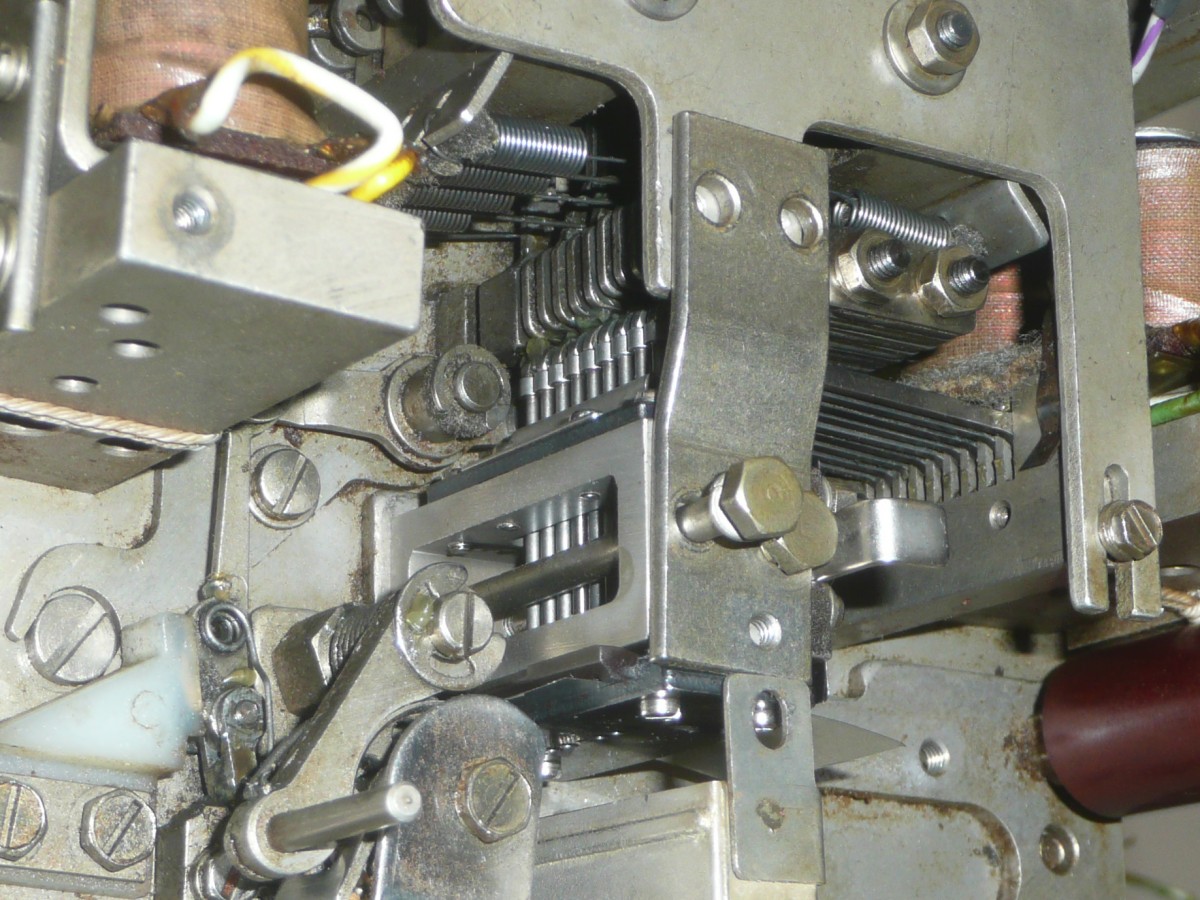
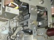
Bug 70: Make an 8-bit BRPE punch block
The 8-bit block
|
|
|
|
We need an 8-bit punch block for our BRPE punch. All we have is 6-bit blocks.
Bug 71: Make cables to connect BRPE punch
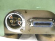
BRPE sockets
|
|
|
|
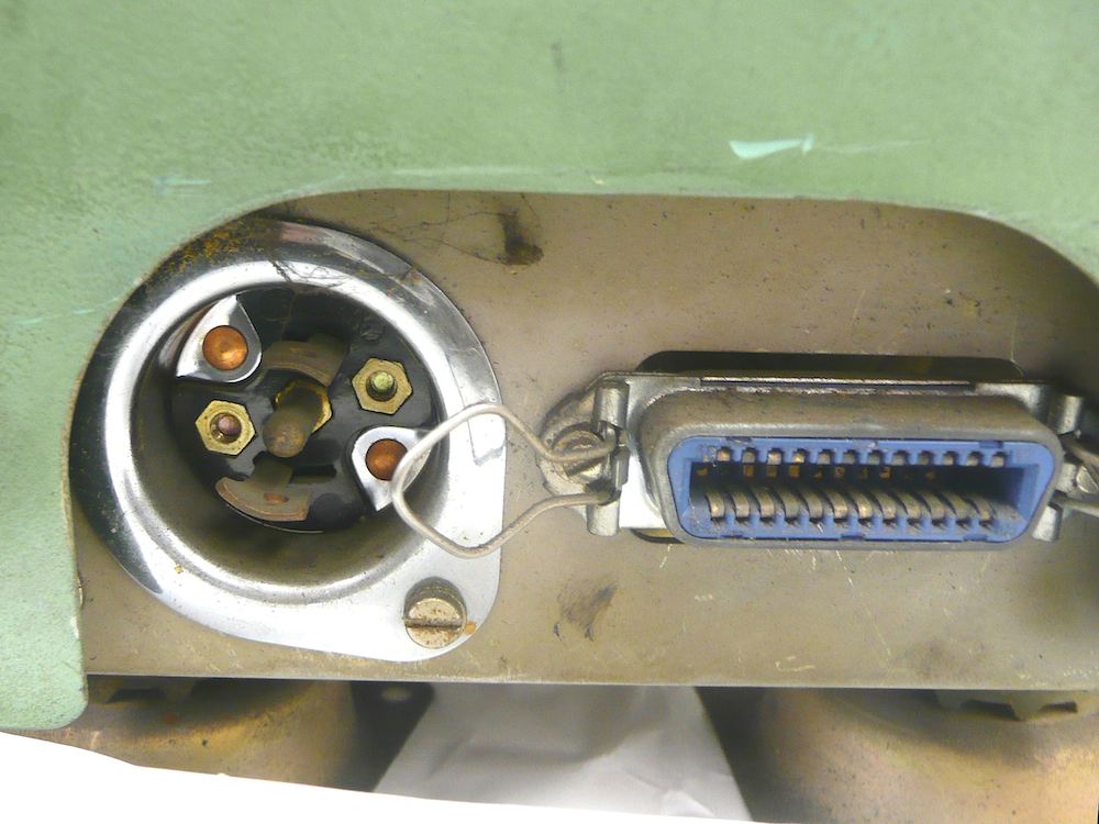
Our BRPE punch came with no data cable and no power cable, just connectors
for the cable in back.
- Create problem, June 4, 2019
We noted missing BRPE punch connectors.
- Progress, Apr. 7, 2025
Make a power cord, test the motor.
- Progress, Apr. 17, 2025
Reverse engineer BRPE wiring.
- Progress, Apr. 21, 2025
Start reverse engineering BRPE controller,
creating Bug 72.
- Progress, May 21, 2025
Cable design completed!
- Progress, Sep 8, 2026
Punch modified to account for current limits in connector.
- Solved? Mar. 22, 2025
Revised design and made the cable.
Bug 72: Reverse engineer Type 75 punch controller
Type 75 backplane
|
|
|
|
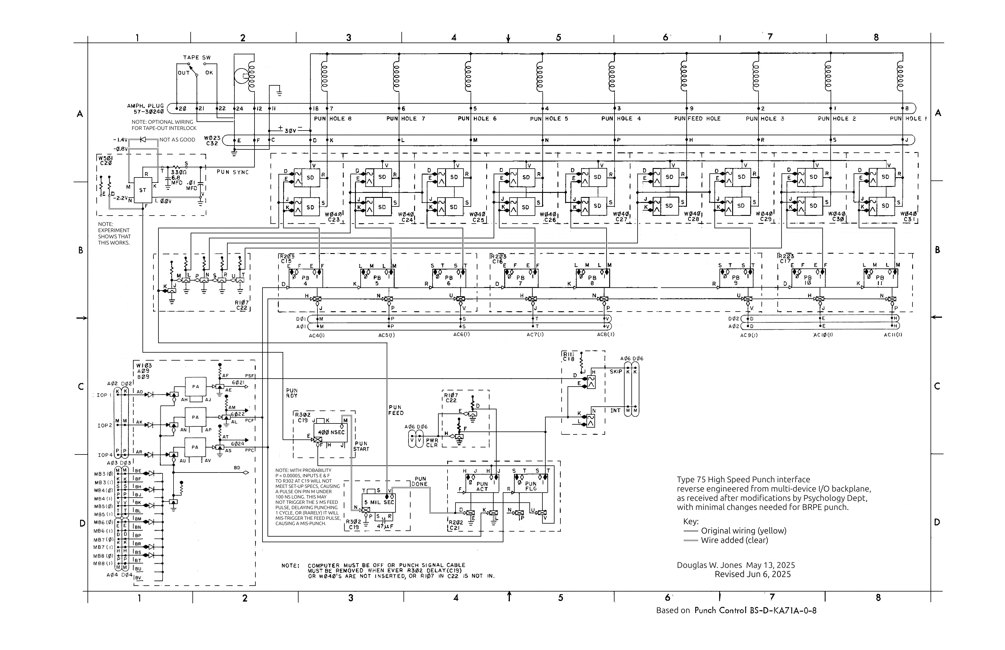
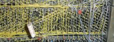
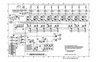
We have a little documentation for the oscilloscope output option that is
part of the
multi-device-controller backplane
at the bottom of the
analog to digital converter rack, but none
of this covers more than cursory details of the Type 75 high-speed
paper-tape-punch controller. There is evidence of modification to this
controller, so we will have to bite the bullet and try to do a complete job
of reverse engineering, first determining how it worked after the Psychology
department modified it to work with their Tally paper-tape punch, and then
determining how to make it work with the BRPE punch it originally supported.
- Create problem, Apr. 21, 2025
Start reverse engineering controller.
Reverse engineered
|
|
|
|
- Progress, May 1, 2025
BRPE punch strobe signal conditioning.
- Progress, May 12, 2025
Trace the controller wiring.
- Solved? May 21, 2025
Reverse engineered,
creating Bug 73.
- Progress, May 28, 2025
Begin testing punch-strobe receiver.
- Solved? May 28, 2025
Finish testing W501 punch-strobe receiver.
- Progress, Sep 8, 2026
Work out which wires need to be removed.
Bug 73: Fix broken and modified W501 Schmitt Triggers
W501 board
|
|

|
|
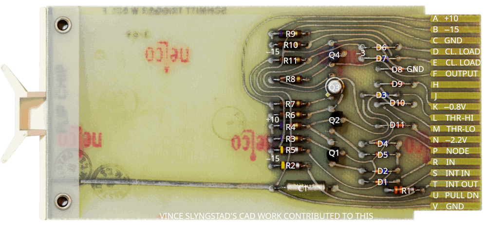
In attempting to figure out how to undo the changes made by Psychology to the
Type 75 High Speed Punch controller, we found that both of our
W501 Schmitt Trigger boards are bad, one modified, one with a bad transistor.
Bug 74: Scan for bad diodes
We have found and replaced many bad diodes in resolving earlier bugs.
Notably, in
bug 49,
bug 61,
bug 64
and
bug 67.
This convinced us to set out on a systematic scan of all diodes on as-yet
checked boards in the CPU and peripherals.
- Start work, July 18, 2025
Row PA finished.
- Progress, July 22, 2025
Row PB started, spare boards started.
- Progress, Sep. 18, 2025
Finished CPU and TTY interface.
- Progress, Sep. 29, 2025
Rows A and B on multifuction I/O backplane started.
- Progress, Oct 6, 2025
Rows A and B on multifuction I/O backplane finished.
- Progress, Oct 9, 2025
Found bad W040A board in row C, creating
Bug 78.
- Progress, Oct 30, 2025
Row C on multifuction I/O backplane finished.
- Progress, Nov. 17, 2025
Scanned all R210 boards in CPU.
Bug 75: Deal with parts mining
Someone has mined parts from the machine for use elsewhere.
Bug 76: Teletype buzzes when turned off
The Teletype should be silent when the local-off-line switch is in the off
position, but instead, it makes a loud buzzing noise.
Bug 77: Teletype interface does not work
First TTY output
|
|
|
|
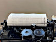
Attempting to send data to the Teletype, the most we get is one clunk from
the mechanism.
Bug 78: Fix W040A solenoid driver
On finding a bad diode on a W040A board, we could not find a schematic
for the W040A, and it obviously differs from the well documented W040B,
so we had to reverse engineer the board to find out the role of that diode
in order to infer its specifications to find an appropriate replacement.
- Created, Oct 9, 2025
Bad W040A board in multifuction I/O backplane row C.
- Solved! Oct 16, 2025;
Reverse engineering completed, board repaired.
Bug 79: Fix high-speed reader-punch supply wiring
The
home-made power supply
for the high-speed paper tape reader and punch
came with a range of poorly done wiring. This needs to be redone, and in
some cases, rethought.
after rewiring
|
|

|
|
- Created, Oct 30, 2025
Old wiring from supply to backplane removed.
- Progress, Nov. 3, 2025
Internal supply wiring spiral wrapped.
- Progress, Nov. 17, 2025
Reverse engineered supply, planned changes.
- Progress, Dec. 11, 2025
It is safe to wire this supply to 120V rack wiring.
- Progress, Jan. 22, 2026
Rewire supply primary.
- Progress, Jan. 27, 2026
Rewire supply secondary and fuse.
- Progress, July 10, 2026
Start new wiring to backplane.
- Solved!, July 21, 2026
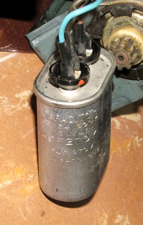
Bug 80: Teletype motor does not spin
During a demo, the Teletype motor did not start when we turned it on.
New capacitor
|
|

|
|
- Created, Jan. 22, 2026
The Teletype stopped working, initial diagnosis.
- Progress, Jan. 27, 2026
Confirm diagnosis of bad capacitor, order new one.
- Solved!, Feb. 5, 2026
Install and test new capacitor. It barely fits.
Bug 81: Teletype drops bit 2
When we typed ABCDEFG the Teletype printed CBCFGFG.
- Created, Feb. 26, 2026
The Teletype stopped printing correctly, initial diagnosis.
- Solved? Mar. 3, 2026
Blocking lever was hanging up in alignment comb.
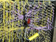
Bug 82: Modify Type 750 for Tally 424 reader
Original Wiring
|
|
|
|
Created, Jan. 22, 2026
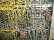
Having completed work on
Bug 34
we need to modify the Type 750C interface to correct errors made by
the Psychology department. These errors include both design errors and
poor workmanship.
- Created, Mar. 5, 2026
Finish Bug 34, start work on cable.
- Progress, Mar. 12, 2026
Undo some of the psychology department's wiring.
- Progress, July 7, 2026
Changes planned and started new wiring.
- Progress, July 10, 2026
New wiring completed, but untested.
Rewired
|
|
|
|
- Progress, July 17, 2026.
Start testing Type 750 interface.
- Progress, July 21, 2026.
It mostly works, but the data is inverted.
- Progress, July 28, 2026.
Inversion fixed, but read errors remain.
- Solved! July 31, 2026.
Verified that errors are not in interface.
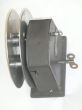
Bug 83: Tape winder stop arm has been cut off
The tape winder
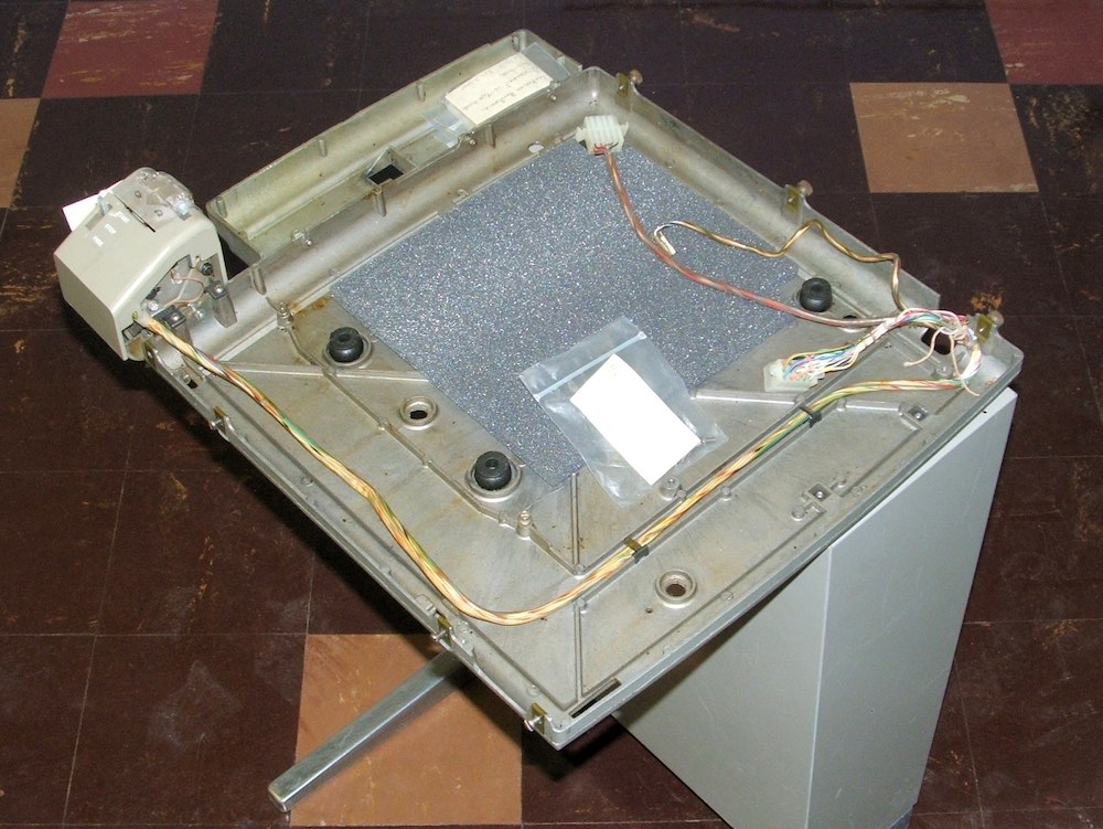
|
|
|
|
Someone cut off the wire stop arm from the tape winder, probably because
it sticks out of the housing and would have made it difficult to pack the
winder for shipping.
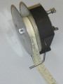
Bug 84: Tape winder reel cannot hold 1" tape
The winder fixed
|
|
|
|
The tape winder came to us with a reel that holds 7/8" wide tape. The
Bunnell catalog indicates that they made reels for 1" tape, so we should
get or fabricate one.
Bug 85: Find a source of Teletype paper
Teletype paper (even new-old-stock) is becoming increasingly rare. If we
are going to make any serious use of the PDP-8, we will need to have a current
paper source.
Bug 86: Repair R210 boards
A bad transistor
|
|

|
|
The R210 is a double-height flip-chip module that implements one bit slice of
the PDP-8 accumulator and ALU. With most of the CPU working, we found that
one operation was failing in just one R210 board.
- Created, Apr. 28, 2026
Bad board identified.
- Progress, Apr. 30, 2026
Reverse engineer and study bad board.
- Progress, May 7, 2026
Found and fixed bad transistor on a spare R210 board.
- Progress, June 5, 2026
Diagnostic work on bad board.
- Solved!, June 19, 2026
Fixed bad board.
Bug 87: Read errors on Tally 424 paper-tape reader
When we tried reading tape on the
Tally 424
high-speed paper-tape reader, we found numerous read errors.
Bug 88: Capstan stalls on Tally 424 paper-tape reader
When we tried reading tape on the
Tally 424
high-speed paper-tape reader, we found that the capstan occasionally stalled.
The problem appears to be entirely mechanical.
Bug 89: I/O Bus termination
Bus Terminators
|
|
|
|
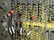
Psychology installed some bus terminators. When we shortened the bus for
debugging just one external device, we investigated this and found that
the terminators Psychology installed were not well thought out. Every time
we add a device to the bus, we will have to move the terminators.
Bug 90: Adjust BRPE punch
The BRPE paper-tape punch manual has a long and detailed section on adjusting
the punch. We will need to follow these instructions.
- Noted, Mar. 29, 2026
Sprocket holes too closely spaced, tape guide a bit low.
Bug 91: Rewire the Type 75 punch controller
As delivered to the University, the Type 75 high-speed paper tape punch
interface was almost certainly wired to support the BRPE pundh, but
the psychology department bought a Tally punch and rewired the interface
to work with that punch. We need to undo the changes Psychology made and
reinvent an approximation of the wiring delivered by DEC.