(none)
  

The University of Iowa's DEC PDP-8

Restoration Log

Contents


Introduction

This is a chronological log of the progress restoring the University of Iowa's PDP-8 computer. Entries are added at the end as work progresses.


Oct. 24, 2013, Initial Assessment

The system
  thumbnail photo of the two electronic racks making up the PDP-8 system; the left one holds the computer, the right one holds I/O dervices  
What have we got? Click on the photos for detail.

Looking through 20-year-old e-mail, I find that we seem to have lost the high-speed paper-tape punch. I doubt we will be punching much tape after we restore the machine, so while that is annoying, it does not stop us from moving ahead.

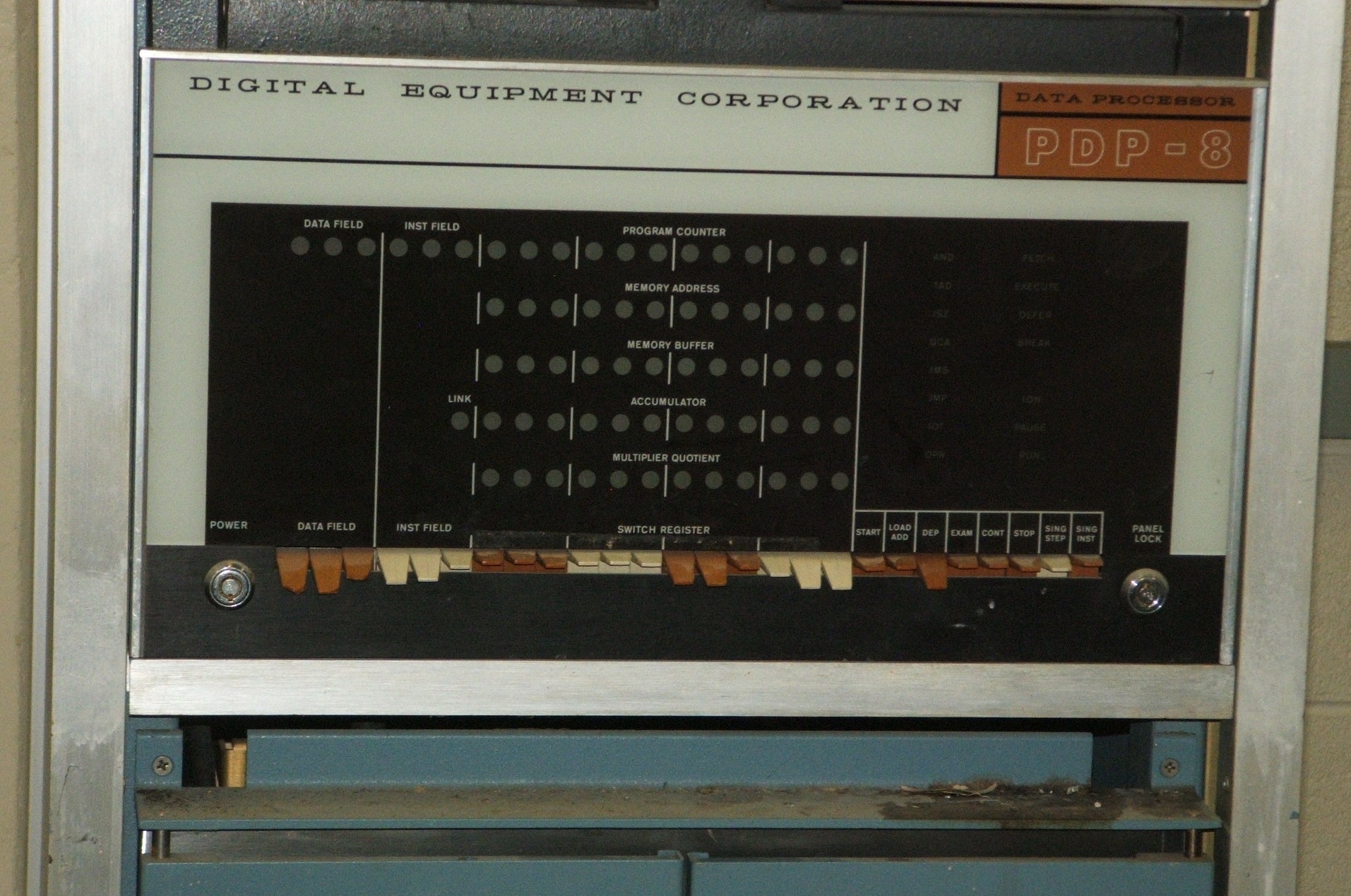
Bug 1: The front panel seems to be in very good shape, but on closer inspection, the plastic switch handles at the left end of the row of switches are chipped, as if they collided with something. They feel loose, and it is probable that the plastic ears that hinge some of these switch handles to their switches have broken. This is a known problem with many models of the PDP-8, and several solutions have been developed over the years.

Fortunately for antiquarians, although the three Ace (tubular) key locks on the PDP-8 are moderately secure, DEC keyed all their computers alike. The key that came with this computer is marked XX2247, and an Internet search on that key reveals that all DEC computers made in the 1960s and 1970s were keyed alike (at least, by default). The three locks are:


Back side
 
  thumbnail photo of the back of the computer rack with the double doors and the rear plenum door they hide all open exposing the back of the computer and the power-control panel   thumbnail photo of the inside of the rear plenum door focusing on the power control panel with its wires, terminal strip and circuit breakers  
Opening the 2 half-width doors at the back of the computer cabinet, you find an inner door, solidly closed with aluminum panels. Notably, this door has rack rails, but they are not spaced for standard 19-inch rack panels, the panels are 16 5/8 inches wide, and the mounting holes are on 2-inch vertical centers. There is an on-off switch and a pilot light on the outside of one of the rack panels near the center of the back door, and a pull-down door latch at the top of the door.

Opening the door, the only hardware mounted on the inside face of the door (aside from a bar that could be used to organize cables) is the power control panel, behind plexiglass. Everything is very clean -- a good sign. The only hardware mounted on the back of the main rack behind the door is the power suply for the computer. The back of the computer and the pile of cables in the bottom of the rack are clearly visible in the photo.
Left side
  thumbnail photo of the left side of the computer rack with the side removed to show the computer with I/O bus cables dangling down from it   thumbnail close-up photo of the left side of the computer in its rack with an array of circuit boards on each side of and below a metal box  
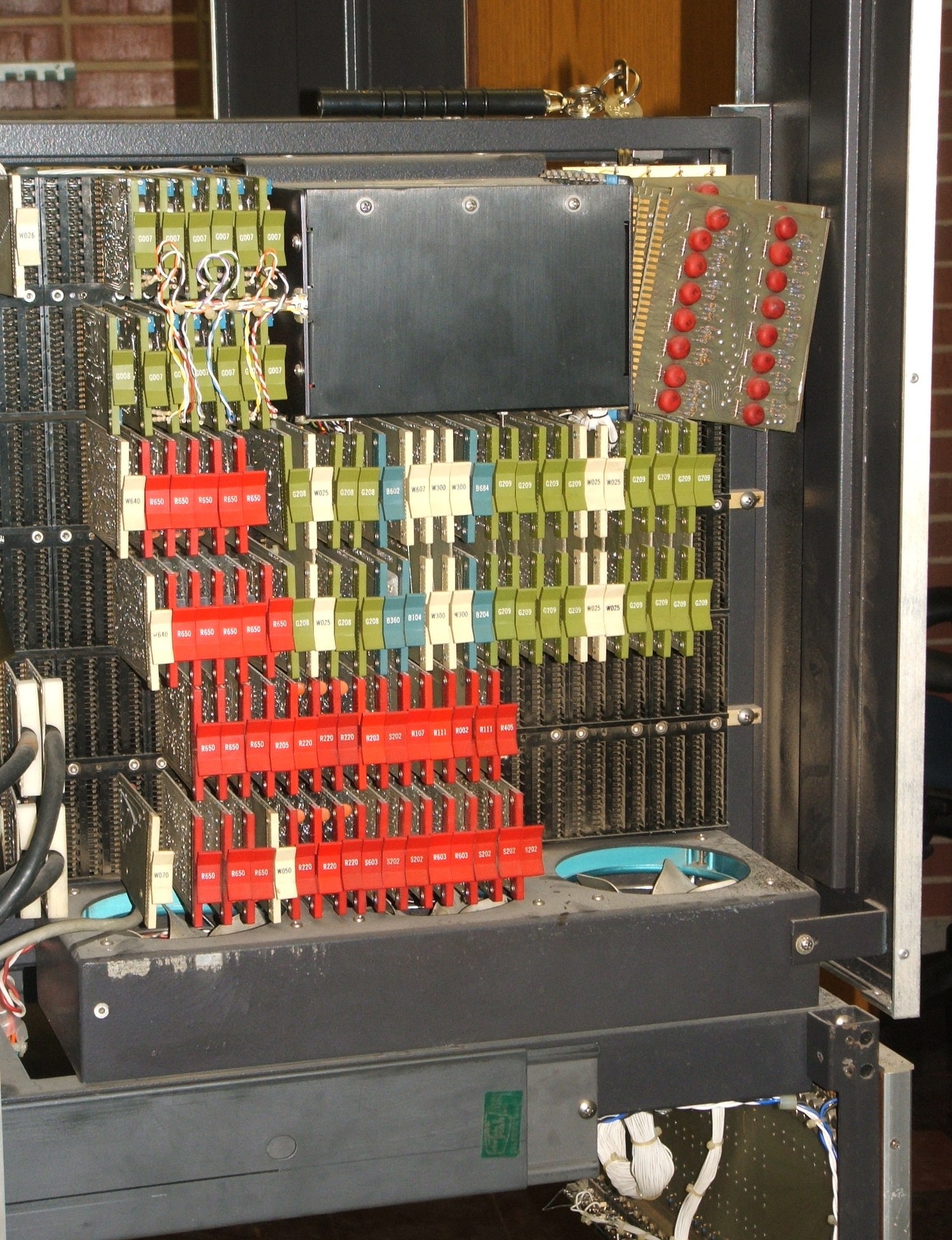
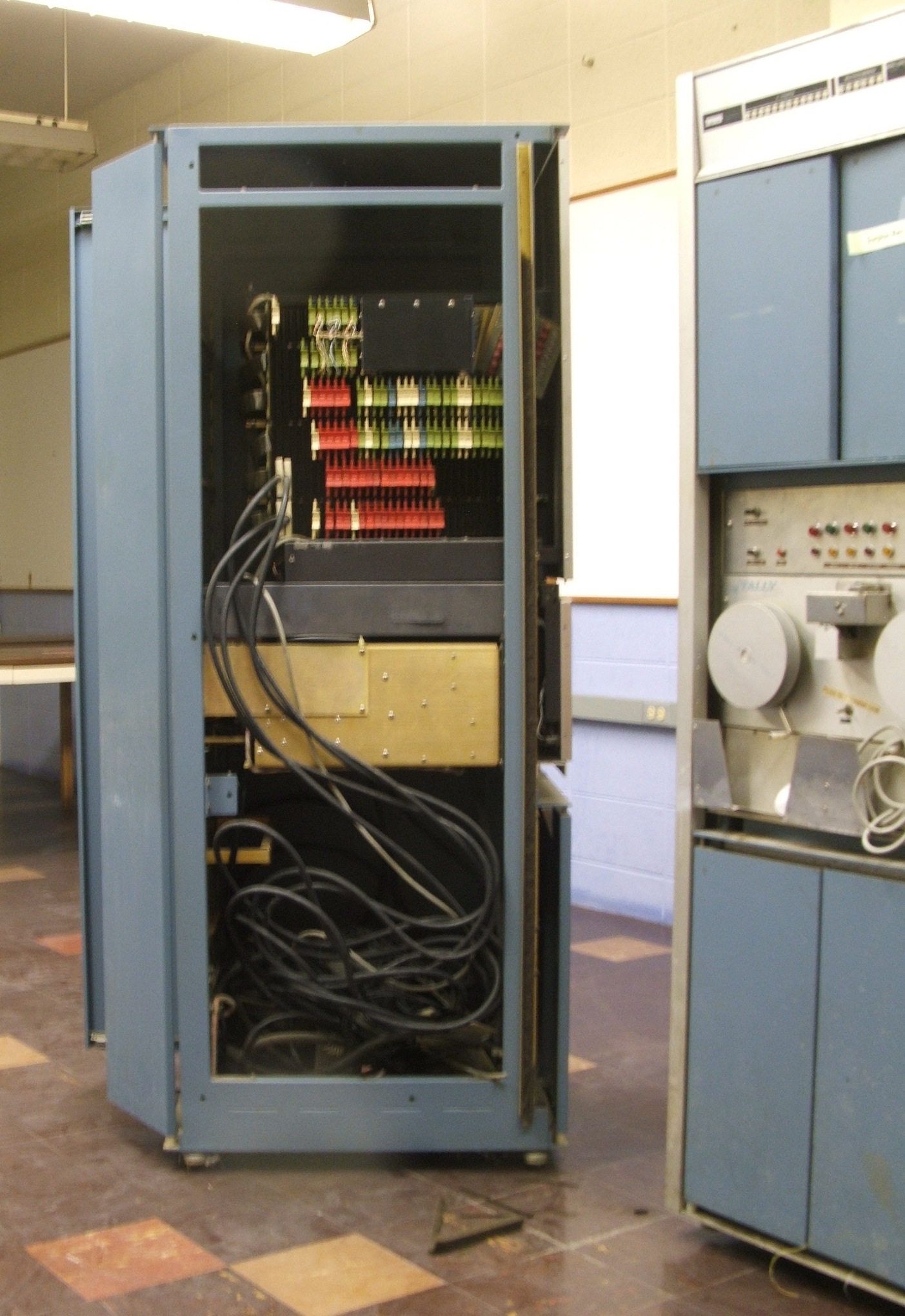
The sides on all of DEC's relay racks can be removed simply by lifting up firmly and then pulling them away. Doing this on the left side of the computer cabinet, you can see how the cables from the computer go down into the cable tangle below, and you can see the side of the power supply, the sides of the rack-slides, and the exposed memory half-backplane of the computer.

Bug 2: You can also see a problem with the machine. There are 8 card-edge connectors facing to the front on the side of the black box holding the core memory. All but one of the circuit cards that should be plugged into these connectors have fallen out, probably simply as the result of vibration. Fortunately, they're all still there.

Right side
  thumbnail photo of the right side of the computer rack with the side removed to show the computer with I/O bus cables dangling down from it; an aluminum channel holding decayed weather stripping runs down one rail  
Bug 3: Pulling off the right side skin of from the cabinet reveals a similar cable arrangement and no obvious problems, until you glance at the floor under the front column of the rack. The same problem was evident on the other side, but went unnoticed (although you can see evidence on the floor in the photo of the exposed left side better than in the photo here). The machine has an aluminum channel holding a plastic foam weatherstrip along both sides of the front. This may have served to control airflow through the cabinet or it may have served to damp vibrations in the cabinet skins in order to control noise. Whatever the case may be, the foam in this channel has decayed to the point that it is brittle, not springy as it once was, and it crumbles to dust when disturbed. We will have to remove it and replace it with something less problematic.

Bug 4: If you look at the close-up photo of the right side of the computer, you can see what look like black ribbon cables. These connect the left and right half-backplanes of the machine. On poking one with a finger, a related problem became evident: These ribbon cables are etched copper foil on some kind of flexible plastic backing, coated with an insulating layer. Unfortunately, the insulating layer has turned to goo. The cables are probably still good, electrically, but they will not survive many flexing cycles from opening and closing the two half-backplanes. We should find an appropriate replacement material for these cables. There are a total of six of them.

Left half backplane
  thumbnail photo of the wire-wrap side of the left backplane; maze of wires connecting thousands of protruding wire wrap pins   thumbnail photo of the top of the backplane; a metal box fills the center, with circuit boards to the left and right, some of them loose   thumbnail photo of the circuit-board side of the backplane; a metal box fills the top center, with rows of circuit boards to the sides and below it  
Bug 5: The next step was to carefully pull the top front of the computer forward on its rack slides. The front panel with its lights and switches and the entire computer slide out, leaving the power supply behind as a counterweight that just barely keeps the rack from falling over.

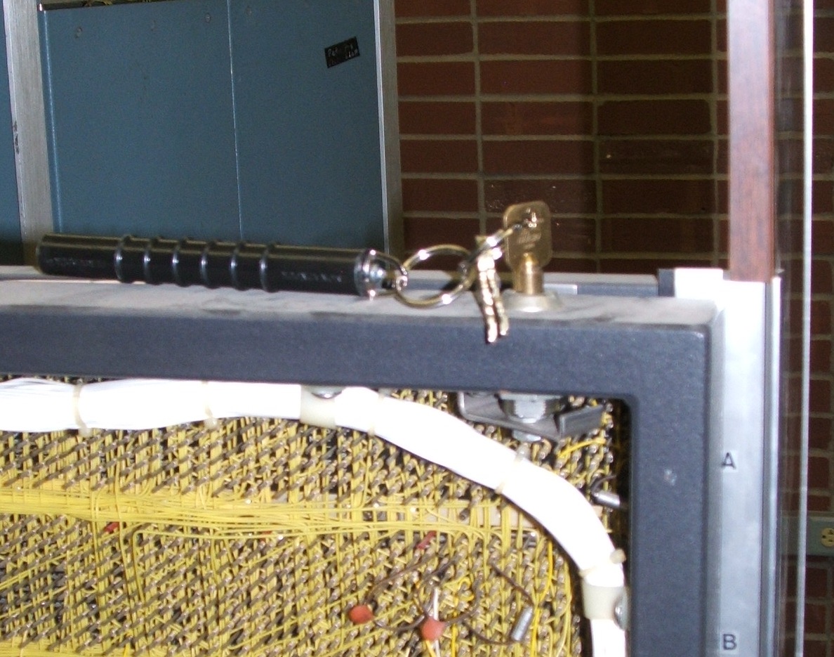
Bug 6: With the computer pulled out on its slides, I took the key to the computer and tried to unlock the latch in the top center rail that holds the two half-backplanes in their closed position. (you can see the key in the upper right of the photo of the exposed left side of the backplane.) That lock had not been opened for at least 20 years, and it was stuck solid. The trick to releasing it is to stick a screwdriver (very carefully) under the top rail to apply force to the latch that the lock turns. It turns counterclockwise, as seen from above.

Once unlocked, the two half-backplanes open out on hinges. The left half is the memory side. The large black box in the center top is the 4K by 12 bit Ferroxcube core memory. A close reading of the quality control label on the memory shows that it was accepted on 10/??/?5. The handwriting is not clear, but it seems safe to read it as some time in October 1965.

The backplane is wire-wrapped with 24-gauge wire. You can see from the photo that it's done by a robotic wire-wrap machine, giving neat diagonal and vertical wire runs instead of the tangled mess that results when a backplane is wired by hand. At the top of the left half backplane, there is a label that is peeling off. Across the top is the preprinted legend

DIGITAL EQUIPMENT CORPORATION
CORE MEMORY
08-291-1000 Type 184A


Right half backplane
  thumbnail photo of the wire-wrap side of the right backplane; maze of wires connecting thousands of protruding wire wrap pins   thumbnail photo of the circuit-board side of the backplane; 6 rows of circuit boards fill all but the lower right corner  
The right half of the computer is the CPU. When the wings are folded out, a label like the label on the other side is exposed. This is also starting to peel off:

DIGITAL EQUIPMENT CORPORATION
CENTRAL PROCESSOR
08-291-0100 Type PDP8-85


Power monitor
  thumbnail photo of a panel exposed when the computer is slid out of its rack with meters, electrical outlets, and some controls  
With the computer pulled out of the rack on its slides, the front of the power supply is exposed. This has the total-hours meter for the machine, reading 26879.0 hours. That comes to almost 1120 days, or a bit over 3 years of total running time. Given that the machine cost $18,000 when new, that means that the actual capital cost of computing on this machine, over its useful lifetime, was about $0.67 per hour.

It's fairly safe to guess that the machine was routinely turned off when not in use -- otherwise, it would have run up far more hours before falling into disuse in the late 1970s. If used for 40 hours per week 50 weeks per year, 26879 hours translates to over 13 years of productive use, roughly 1966 to 1979.

This panel is only accessible when the machine is undergoing maintenance. It has power outlets where the technician can plug in small test equipment, an auxiliary on-off switch, and a meter to monitor the power supply output (with a switch to select which output voltage it monitors).

Oct. 25, 2013, More Assessment

Front panel
  thumbnail photo of the pdp-8 front panel, a row of 26 plastic-handled toggle switches between 2 key-operated switches with 5 rows of lights above the switches, 12 per row except the top row which has 18  
Bug 1: This picture was missing from yesterday's collection. The front panel of the PDP-8. If you look at the leftmost switches, you can see how chewed up they are. They are loose, too, but considering that this PDP-8 only has 4K of core, they are of little importance.

Bug 5: The inch-deep space immediately below the front panel is where the table-top goes. The drawing on page 204 of the PDP-8 Users Handbook (F-85 5/66), also on page 7-4 of the PDP-8 Maintenance Manual (F-87 2/66) shows a table top cantelevered 18 inches beyond the front edges of the rack skins, with its left side flush with the outside edge of the rack skin and its right side protruding an extra 9 inches. The drawing on page 1-12 of the Maintenance Manual shows as gull-wing table with stabilizing legs attached to the front of the cabinet that looks like the front half of the gull-wing table DEC sold for the table-top model, documented in the previously cited drawing. The legs under the gull-wing table would be the ultimate insurance against having the rack fall over. As received, the rack is definitely unstable when the computer is slid all the way out.

The ADC rack
  thumbnail photo of the front of the ADC rack, with double doors closing the top and bottom and the center dominated by 2 paper-tape reels   thumbnail photo of the side of the ADC rack with the side panel removed so you can see cables draped between electronic assemblies   thumbnail photo of the inside of the rear plenum door of the ADC rack with cables draped down from 2 connector panels at the top and 2 power supplies attached to the panels at the bottom  
The second rack that goes with this PDP-8 was built as an analog-to-digital converter rack, and then the University of Iowa Psychology department added several other peripherals. At this point, only the Tally high-speed paper-tape reader is obvious. Here, we'll go through them from top to bottom.

The ADC multiplexer
  thumbnail photo of the top front of the ADC rack, at the top is a panel with a row of lights, below that, the double doors are open revealing a wire-wrap backplane   thumbnail photo of the back f the backplane at the top of the ADC rack, with rows of circuit boards, but also many vacancies  
At the top is an analog to digital converter and multiplexer. Looking at the backplanes with the top cabinet doors open, there is ample evidence of field modification. The top two backplane modules (4 rows of boards) are apparently the stock ADC and multiplexer, but the bottom backplane module looks homebrew. Among other things, much of the white, pale yellow, red and blue wiring is 30-gauge wire, the wrong gauge wire for DEC's older wire-wrap backplanes. They are supposed to be wired with 24-gauge wire. (30-gauge only came in when DEC switched to 2-sided card-edge connectors, a change they made when they moved to TTL logic).

The Tally reader
  thumbnail photo of the front of the Tally reader, with tape reels on each side of the read-head, fanfold tape bins below, and a panel of indicator lights above   thumbnail photo of the back of the Tally reader, with a motor, gearboxes and pullies, partly obscured by wires draping from the indicator panel above  
The Tally paper-tape reader looks like it is essentially unmodified, although the drape of wires from above obscures it. Where the interface to this reader is, and where the cable is that mates with its connector is another matter. The home-brew fanfold tape bin below the reader is nicely made, and should pose no problems.

The mystery
  thumbnail photo of the wire-wrap backplane behind the double doors at the bottom of the ADC rack, with loose wires draping from it down to the floor   thumbnail photo of 4 rows of circuit boards plugged into the back side of the backplane at the bottom of the ADC rack  
Whatever this is at the bottom of the rack is scary. Loose wire wrap wires dragging on the floor are not encouraging, and although some of the wiring is factory original, there is lots of homebrew work here, with 30-gauge wire. The switches at the bottom saying things like "MUST BE ON FOR DR RANDALL S PROGRAM" makes it very clear that this was a one-off thing.

The Teletype
  thumbnail photo of the Teletype from the front left, with a keyboard in fron of a typing mechanism all supported by a pedestal   thumbnail close-up photo of the Teletype paper-tape reader hanging by its wires from the front left corner beside the keyboard   thumbnail photo of the back of the Teletype with wires hanging down out of the right rear corner  
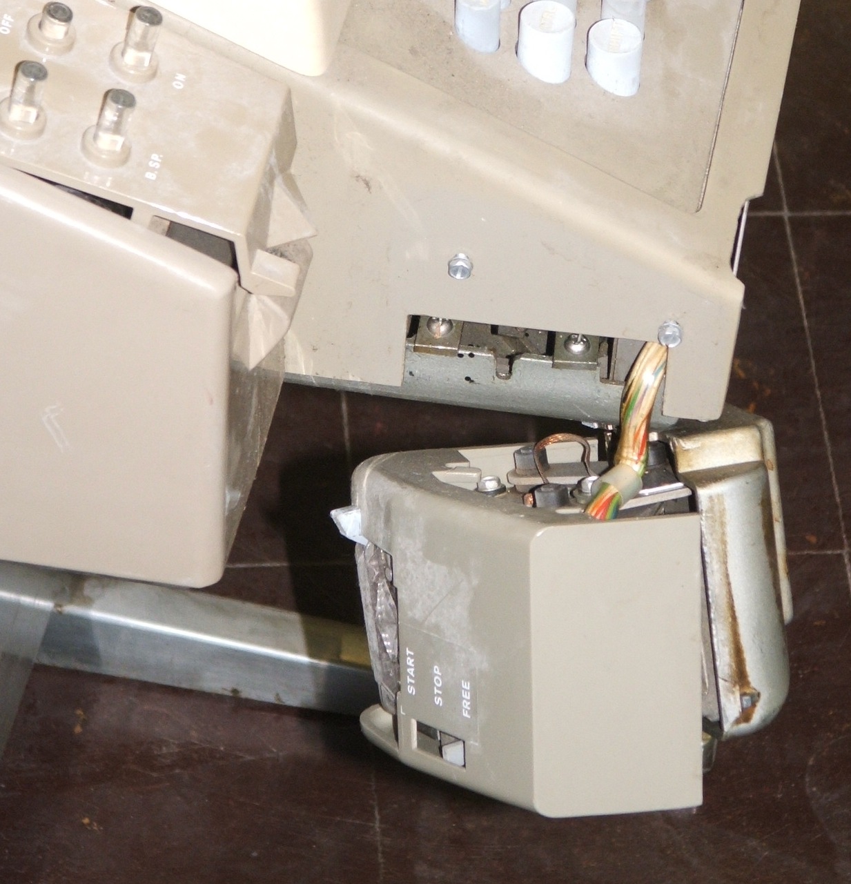
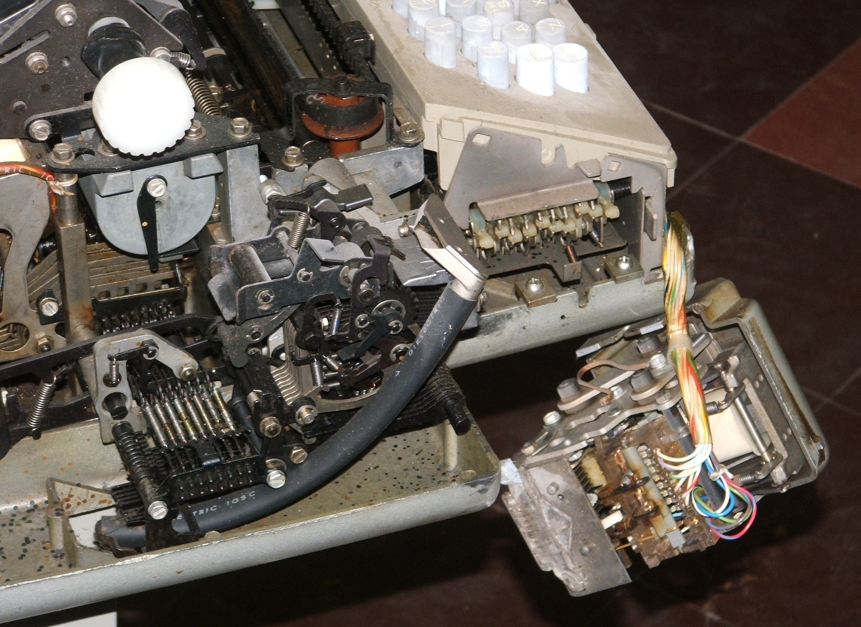
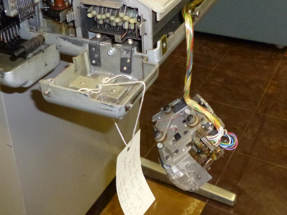
Bug 7: The Teletype that came with this machine is not in great shape. The paper-tape reader has been broken off and may be difficult to repair. The cast ears that attached the frame of the paper tape reader to the frame of the Teletype are broken off. We need to determine if the reader can be repaired.

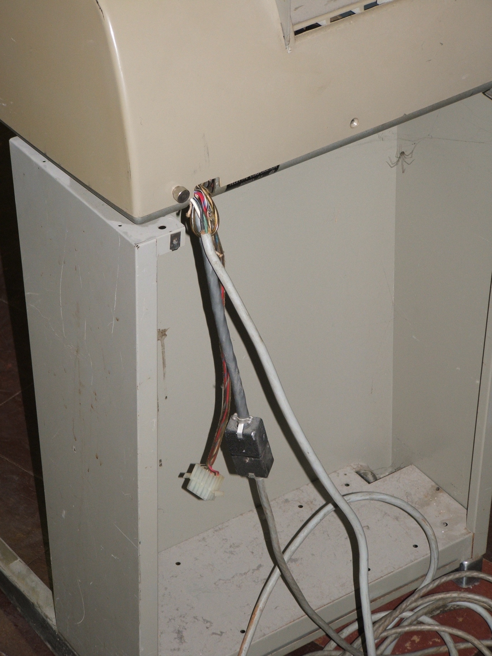
Bug 8: The electrical wires at the back are another puzzle. Normal Teletypes have one power cord and one data cable. This seems to have two data cables. And all the wires have been pulled out of their strain reliefs and will need to be redone before anyone even thinks about plugging this in.

Bug 9: Also, although impossible to see in the photos, the rubber head on the print hammer is shot. That's common with old teletypes, and apparently easy to fix with a piece of vinyl tubing as a replacement hammer head.

Oct. 28, 2013, Yet More Assessment

Balance
  thumbnail side-view photo of the PDP-8 extended from its rack on its rack slides, with the side of the rack removed  
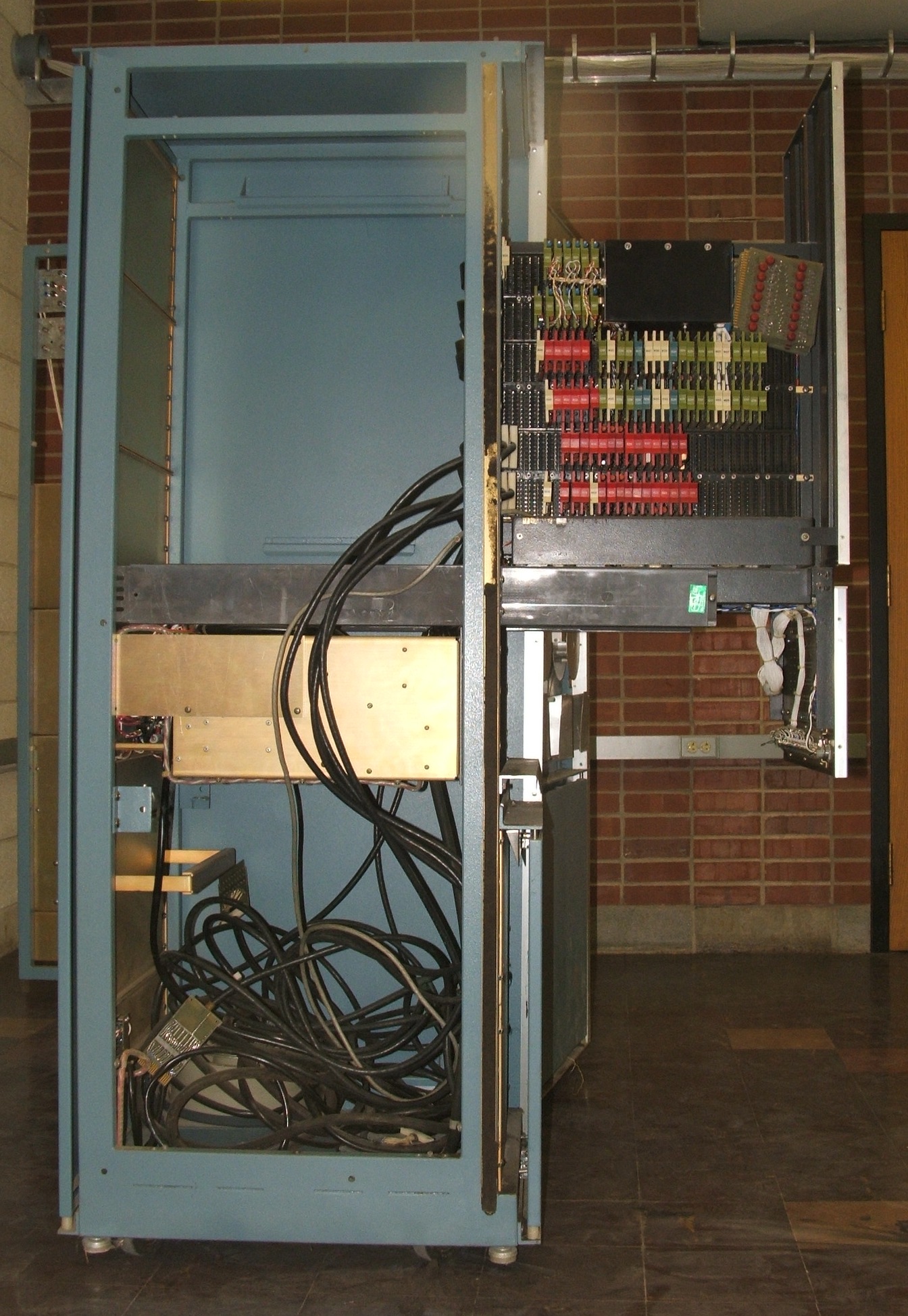
Bug 5: This picture was missing from the previous collections. Here you can see how the computer slides forward on rack slides. With the side-skin of the rack removed, you can also see a leveling foot that is fully retracted into the cabinet, that would hit the ground several inches forward of the cabinet casters if it was screwed down! That would greatly improve the balance of the cabinet when the computer is out as in this photo!

Suggested rule: Never slide the computer out of the rack unless the leveling feet are screwed down to carry the weight of the rack.
Backplane latch
    thumbnail close-up photo of the latch that can hold the two half backplanes closed against the frame; the key is in the unlocked latch and one half backplane is in the closed position    
Bug 6: This picture was also missing from the previous collections. Here you can see how the backplane latch on the CPU is simply a bent piece of metal screwed to the back (bottom) end of the lock. Whe turned to the locked position, the latch engages similar bent hooks screwed to the backplane mounting frames.

Power supplies
 
thumbnail close-up top-view photo of the PDP-8 power supply, with many large capacitors and a large transformer   thumbnail photo of of the power supplies on the inside of the rear door of the ADC rack, more big capacitors and 3 transformers  

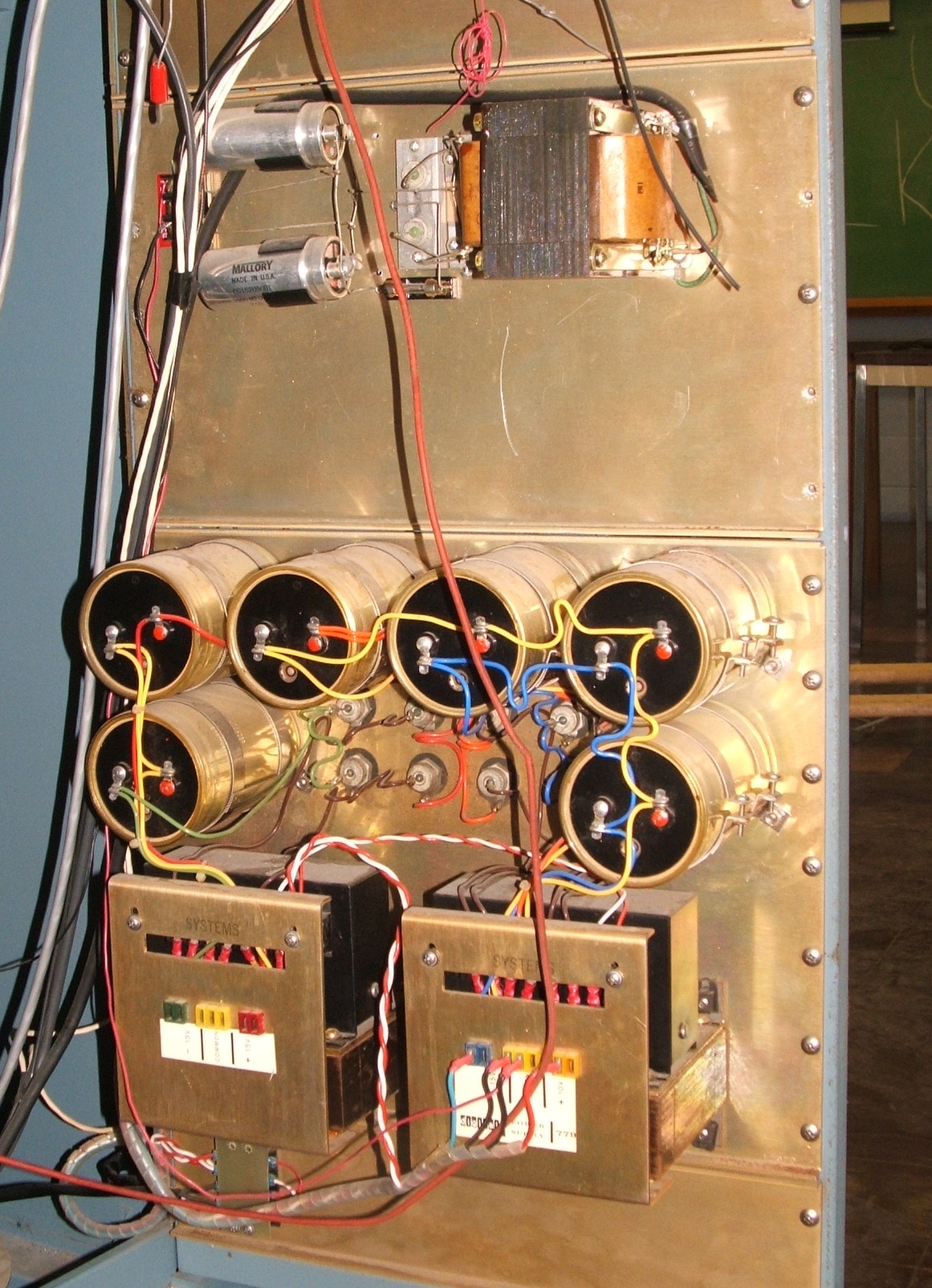
The power supplies are extremely simple, by modern standards, consisting of transformers, rectifiers and filter capacitors, with nothing resembling a voltage regulator. This is misleading, at least in the case of the CPU, the transformer itself is the voltage regulator, using controlled saturation of the magnetic circuit to give constant output voltage over a wide range of input voltages.

Bug 10: The electrolytic capacitors are a problem. They have not been used in approximately 30 years. They will need to be reformed by carefully running a very low current through them to rebuild the dielectric. This would be easier if the connections to the capacitors were made with screws -- the fact that all these connections are soldered means we must either unsolder them or try to reform the dielectrics of each capacitor bank in parallel, a risky proposition.

Decayed door gasket
        thumbnail photo of decaying weather stripping in an aluminum channel attached to one of the rack rails        

Bug 11: There is another decayed foam strip that needs to be dealt with. As with Bug 3, this involves foam strips in aluminum channels. These strips are less conspicuous than the ones noted previously; they serve either to seal or damp vibrations in the rear doors of each cabinet.

Bus cables?
  9 strands of coaxial cable connecting 2 printed-circuit board paddles that can plug into backplane slots   9 strands of snarled coaxial cable connecting 2 printed-circuit board paddles that can plug into backplane slots  

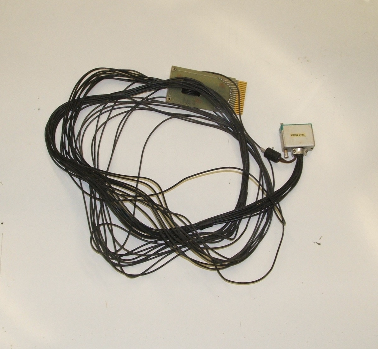
Here are some of the cables that were tangled in the bottom of the computer rack. At this point, the main I/O bus cables were left in the rack. These two cables use standard Flip-Chip boards as connectors, so they plug backplane slots at both ends. The conductors are coaxial cables, 9 per board. DEC used 6 such cables to carry the PDP-5 and PDP-8 I/O bus from one device to the next as the daisy-chained I/O bus. Each of these cables is made of 9 coaxial cables.

One of these two cables has come unbundled in the middle and is very snarled. One of the conductors in this snarled area has been cut.

Analog cable?
  4 strands of snarled coaxial cable connecting a printed-circuit board paddle that can plug into a backplane slot with individual connectors  

This cable has only 4 strands of coax in it, two ending in BNC connectors, one ending in a big fat connector, and one twin banana plug. The worst-case guess at this cable's purpose is that it was some kind of special-purpose analog cable related to a long-finished psychology experiment.

I/O interface cables
 
Multiple strands of coaxial cable connecting a 36-pin connector to 2 printed-circuit board paddles that can plug into a backplane slots   9 strands of coaxial cable connecting a printed-circuit board paddle to a 36-pin connector   9 strands of coaxial cable connecting a printed-circuit board paddle to a 36-pin connector labeled TALLY READER  

The other three cables were, apparently, connectors to various I/O devices. They have standard DEC card-edge connectors on one end, and specialized device connectors on the other end. One cable is Y-shaped, with two card-edge connectors because it has more than 9 data lines. The other two have 9 lines each. One is clearly marked "TALLY READER" -- the cable to the high speed paper-tape reader?


Oct. 31, 2013, Component Identification

The bottom rear center of the main pull-out frame holding the half-backplanes of the CPU has a metal tag attached giving the machine's serial number, 85.

|d|i|g|i|t|a|l| EQUIPMENT   PDP-8
CORPORATION
MAYNARD MASSACHUSSETTS 85

The power control panel on the inside of the back door of the computer rack has a sticker giving its model number:

|d|i|g|i|t|a|l|   POWER 834
CONTROL

The power supply for the CPU is Type 708.

The serial number on the FERROXCUBE memory module on the left half-backplane is 51-238-71. The model number field is blank.

The text at the right-top of the ADC rack (to the right of the word-length knob) gives the model numbers as follows:

A-D CONVERTER 138E
MULTIPLEXER 139E

There is a University of Iowa inventory tag on the right skin of the ADC rack. The inventory number is 178448.

The paper tape reader in the ADC rack has two serial number labels. The label from the vendor, on the center right top, seen from the back, is printed in red ink on aluminum and reads:

SERIAL 9789
TMC
TECHNICAL MEASUREMENT
CORPORATION

the label from the manufacturer on the far right top, seen from the back, is printed in negative, blue on aluminum, reading:

SERIAL NO 351/0811    

TALLY
  424 TAPE READER

The topmost of the two power supplies on the back door of the rack has no markings. Is it some kind of homebrew supply?

The bottomost power supply on the back door of the rack has the following label:

|d|i|g|i|t|a|l|     POWER   779
SUPPLY

Bug 11: When this bug first came to light, only one gasket was noted on the back door of each cabinet -- the gasket on the latch side of the door against which the door slams when closed. There is a second identical gasket (equally decayed) on the hinge side, sitting between the doorjam and the edge of the door. You can only see this when the rack side skin on the hinge side is removed and the door is open.


Nov. 4, 2013, Cable Puzzles

Tally reader cable
      9 strands of coaxial cable connecting a printed-circuit board paddle to a 36-pin connector labeled TALLY READER      
This cable is, as the label on the connector says, the cable for the Tally high-speed paper-tape reader. The plug fits, so the cable was plugged into the reader with the other end left dangling. The Tally 424 reader, in its rack-mount configuration, cost $825 according to Martin H. Weik, A Fourth Survey of Domestic Electronic Digital Computers, Ballistic Research Laboratories Report No. 1227, Aberdeen Maryland, January 1964; page 85. Selected pages of the manual for this reader were included in the LGP-21 Hardware Maintenance Manual found in the collection of the Computer Museum of America and scanned by by Tom Jennings. (See Tape Reader Manual — Model 424, Tally Register Corporation, 1962.)

The Tally manual gives the maximum data rate as 60 characters per second. From this, we can conclude that the little 2-pin Jones plug hanging from the back of the cable connector for the printer was to feed 110 VAC to the motor. 8 of the 9 data lines in the cable must be for data, with the final line being the strobe signal generated by the commutator on the capstan or something equivalent.

Bug 12: Find where the other end of the paper-tape-reader cable is supposed to plug in. It is possible that it was plugged into one of the homebrew interfaces in the same rack as the reader.

Bug 13: Build the necessary secondary cable to bring 110 volt power from the power distribution panel on the ADC rack to a Jones plug to power the paper tape reader.

Teletype data cable
      thumbnail photo of the back of the Teletype with a short section of poorly secured cable ending in a 12-pin Jones plug      
The Teletype data cable is a 6-conductor cable connecting to the Teletype through a 12-pin Jones plug. This plug was apparently salvaged and repurposed for this, judging by the solder on unused terminals. The far end of the data line was cut, but it matches the cut end of a wire hanging from the W070 teletype interface connector plugged into slow MF30 of the computer (memory-side, row F, column 30). To make this clear, the connector at the Teletype end was unplugged, and the cut ends of the cable were knotted loosely to keep them together, leaving them, hanging from the W070 card. Connecting the computer to the Teletype will require addressing 3 distinct bugs:

Bug 8: As already noted, the wires at the back of the Teletype have all been pulled out of their strain relief.

Bug 14: The cut cable needs one of three things: Either replace the entire length of the cable up to the connector where it mates with the Teletype, splice the cable where it was cut, or add a connector where it was cut. It would be sensible to use a connector compatible with the one at the back of the Teletype, but see Bug 15.

Bug 15: The 12-pin Jones plug in the Teletype cable is not really appropriate. If our restoration philosophy allows, replace it with a 6-pin connector. There may be no standard for this, but 6-pin Jones plugs are still available.


Nov. 7, 2013, Yet More Component Identification

There are some difficult to see aluminum labels hiding inside the machine. Each wing of the computer has its own serial number on an aluminum label on the top rear vertical member, adjacent to the hinge. The label faces inward toward the connector blocks and is obscured by the ribbon cables that connect the two half backplanes.

The memory side aluminum label reads:

|d|i|g|i|t|a|l| EQUIPMENT   M8 100
CORPORATION
MAYNARD MASSACHUSSETTS

The CPU side aluminum label reads:

|d|i|g|i|t|a|l| EQUIPMENT   8P-103
CORPORATION
MAYNARD MASSACHUSSETTS

Hunting around the mystery backplanes, more labels came to light. Each machine-wire-wrapped mounting panel has an aluminum label on the inside of the left mounting plate (when seen from the rear). In general, these labels were invisible until the adjacent boards were removed. In some cases, there were also paper labels. The top panel of the ADC rack has this aluminum label:

|d|i|g|i|t|a|l| EQUIPMENT   138E-14 
138E-13 
CORPORATION
MAYNARD MASSACHUSSETTS

The panel immediately below on the ADC rack has two paper labels immediately next to the aluminum one:

DIGITAL EQUIOMENT CORPORATION
MULTIPLEXER CTRL
08-291-2600 Type 139

DIGITAL EQUIOMENT CORPORATION
AD Converter
08-291-8100 Type 138E

The aluminum label on this panel reads:

|d|i|g|i|t|a|l| EQUIPMENT   AA03- 
 10 
CORPORATION
MAYNARD MASSACHUSSETTS

The next panel down, one of the mystery panels that was obviously hand wired, has a paper label on the outside of the right mounting plate, when seen from the rear. This label reads

|d|i|g|i|t|a|l|     MOUNTING   1943
PANEL

In the previous attempt to document the Tally paper tape reader, the full manufacturers label was not transcribed. It reads:

SERIAL NO 351/0811  

TALLY
  424 TAPE READER
MOTOR 60 CYCLE 115 VOLTS .44 AMPS
FUSE 6/10 AMP MDL (BUSS)
CAPSTAN DRIVE MECHANISM
                          24   PULSE VOLTS
  50   COIL OHMS  

The bottom two mystery panels also have labels on the inside of the left mounting plate, when seen from the rear. The top one of the pair has two paper labels and an aluminum label. To the extent they are legible, the paper labels read:

DIGITAL EQUIOMENT CORPORATION
OSCILLOSCOPE DISPLAY
08-291-3400 Type 34D

DIGITAL EQUIOMENT CORPORATION
///ME OPTION & CLOCK
//-/91-2500 Type 151

The aluminum label on this panel reads:

|d|i|g|i|t|a|l| EQUIPMENT   340 18 
 10 
CORPORATION
MAYNARD MASSACHUSSETTS

At the bottom left of the rosewood veneer front of the computer just above the front panel there are two yellowed pieces of paper taped to the front. They contain typed text:

HIGH SPEED RIM LOADER MOD
 7756- 6014 6011 5357 6016
 7762- 7106 7006 7510 5374
 7766- 7006 6011 5367 6016
 7772- 7420 3776 3376 5356
 7776- 0000 5306
       
  TAPE COPY ROUTINE:
  200   7200  6016  6026  6011
        5203  6021  5205  5200

Mystery power supply
      thumbnail closeup photo of a terminal strip, 2 electrolytic capacitors, some stud rectifiers and a transformer, mounted on a metal plate and partly obscured by dangling wires      
The mystery power supply on the rear plenum door of the ADC rack has dymo label tape marking the PLUS and NEG outputs at the hinge side of the panel. This makes it very clear that this supply is homebrew work.

Cut power wires
      thumbnail photo of a terminal strip inside the bottom right rear corner of the ADC rack, next to the fan, with 5 cut off wires attached to it      
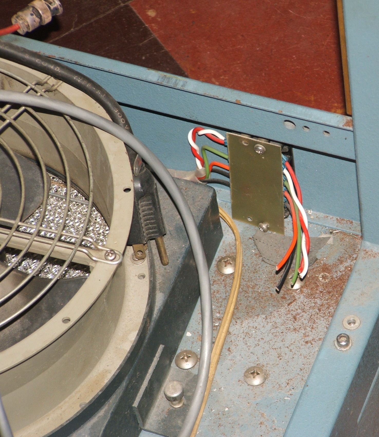
Bug 16: The power distribution wiring harness in the ADC Rack ends very abruptly at a set of cut wires at the right rear corner of the rack. The power cabling for this rack will need a careful study and repair before any attempt is made to apply power.

Miscellaneous photos
  thumbnail photo of the back side of the PDP-8 front panel, a printed circuit board above a row of switches with neatly bundled wires draping down, some connected to the switches   thumbnail photo of the circuit boards plugged into the PDP-8 memory half backplane, 6 rows of boards with metal box filling the middle of the top two rows  
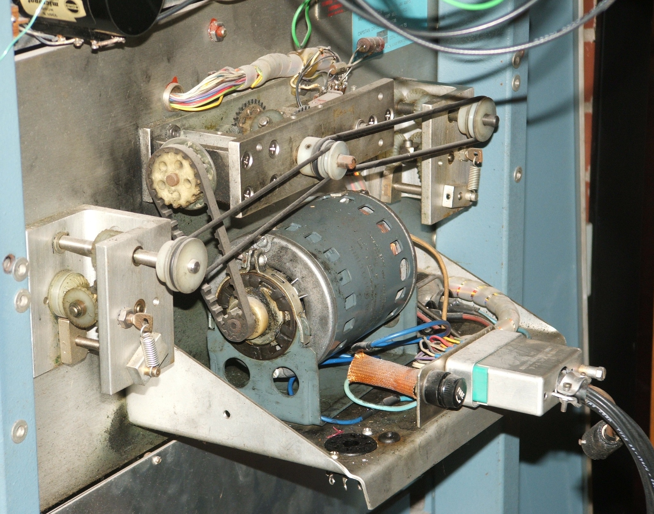
  thumbnail photo of the back of the Tally paper-tape reader; a motor on a bracket has a belt drive up to the middle gearbox, and belt drives from there to the left and right gearboxes; a cable plugs in by the motor   thumbnail photo of the two top panels in the ADC rack rear plenum door one with three rows of connectors, one with two rows  
Several items already documented were worthy of better photos: There was no good photo of the back of the computer's front panel nor of just the boards on the left (memory) side of the computer. The back of the Tally reader with it's many differentials wasn't clear, nor was there a photo of the Tally reader cable properly connected to the reader. Finally, there was no photo of the plug side of the ADC rack's analog interface panel.

Missing portraits
  thumbnail photo of the teletype left of the computer rack left of the ADC rack; the top half of the computer rack is fake wood paneling; everything else is painted metal   thumbnail photo of the computer rack; the top half of the computer rack is fake wood paneling; below that is the front panel, everything else is painted metal  
More missing photos: There was no good portrait of the whole system, nor was there a good portrait of just the computer rack.


Nov. 13, 2013, First Bug Dismissal

Bug 6: There is a trick to unlocking the latch that holds the two half backplanes of the computer in their folded configuration: With one hand, squeeze the two halves together while turning the key with the other hand. This releases the friction on the latch and allows the key to turn. Problem solved!


Nov. 22, 2013, Second Bug Solved, TTY Work

Map of 34D Scope Display
  thumbnail photo of the boards plugged into the backplane at the bottom of the ADC rack, with an overlay identifying the device they apply to  
Bug 12: The Module Utilization List D-34D-0-3 Rev J, for the Type 34D Oscilloscope Display documents the display interface as part of a multiple-device backplane wired for numerous devices, including the Type 750C High Speed Reader and the Type 75E High Speed Punch. While the backplane at the bottom of the ADC rack has labeling that suggests differences from that documented on the Module Utilization List, comparison with that list confirms that these two interfaces are indeed present, although modified by field wiring. Therefore, the other end of the high-speed reader cable was plugged into the slot indicated by the module utilization list. Problem solved!

The plastic shroud over the Teletype was removed, exposing the glorious electromechanical complexity of the Teletype and allowing assessment of the damage to the paper-tape reader. The assessment work remains to be done.


Nov. 25, 2013, TTY Work

The Teletype unshrouded
  thumbnail photo of the teletype mechanism from the rear, with the motor in the center foreground and a very complex mechanism behind it   thumbnail close up of the right rear corner of the teletype mechanism; there are 8 15-wire connectors beside the mechanism   thumbnail photo of the right side of the teletype mechanism, with electronics in the foreground and mechanical complexity behind  
Bug 8: Before taking photos of the Teletype with its covers removed, the power cord was carefully pushed back into its strain relief. It is just a nylon screw-down clamp, not good for great tension, but better than nothing. There is a mounting hole that could hold a strain relief for the data cable, but no evidence this cable ever had a strain relief. In addition, the apparent second data cable appears to be integral to the wiring harnesses inside the Teletype. The 15 conductor Mate-N-Lok connector on the end is the same kind of connector Teletype used internally. Perhaps it plugged into some missing optional component?

The Teletype label on the lower back, just to the right of the power cord, reads, in negative, black ink on aluminum:

TELETYPE CORPORATION
MODEL 33   CSAM
SUPPLY INPUT: 115 V. 60~ A.C. 4 AMP. MAX.
SIGNAL INPUT: 50 V. MAX. D. C. 0.1 AMP. MAX.

The right side of the typing unit chassis, just below the carriage motion belt, has a label reading, in negative, yellow ink on aluminum:

REMANUFACTURE DATE: 10/30/74:
BY   CARTERFONE COMM. CORP.

Reader & punch
  thumbnail close up of the left front corner of the teletype mechanism; the paper-tape reader is hanging by its wires from the side of the keyboard  

Bug 7: With the plastic covers removed, the broken brackets for the paper-tape reader are clearly visible. The best guess we can infer from the nature of the break is that someone tried to use the paper-tape reader as a handle to lift the Teletype. Obviously, the cast metal frame was not strong enough for this. The cast metal frame was removed from the bottom of the reader in preparation for building new mounting brackets for the frame. Although there are 5 screws on the bottom holding the reader, 4 of them are leveling screws. Only the central (black) screw actually holds the reader to the frame casting.
Broken cover
  thumbnail photo of the inside of the Teletype lid; the plexiglass window is scratchedm, filthy and completely broken free from the ABS plastic body  
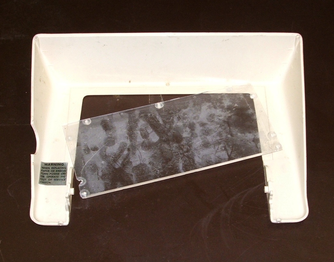
Bug 17: The transparent plastic insert in the Teletype cover is entirely broken free from its mounting. It appears that it was thermally riveted to the inside of the cover. Should this be replaced or repaired? It is also filthy, and one of the ears that clip the cover to its hinges is broken off.

Hammer
  thumbnail photo of the Teletype print mechanism; the ribbon spools are by the keyboard on each side of the hammer, with the print cylinder between the hammer and the platten  
Bug 9: The bug report on the mushy print hammer did not include a good photo. Here is one.

Tagged and shelved
  thumbnail photo of a shelf unit holding all of the removed Teletype parts, each tagged with where it came from  
Finally, all of the Teletype parts that were removed were tagged to clearly identify where they had been removed from and give hints, on the tags, about proper reinstallation.


Dec. 12, 2013, TTY Work, Supplies

The lab now has a broom, dustpan, paper towels, spray cleaner, WD-40, and scouring pads. Most of the dust from the crumbled gaskets has been swept up.

Bug 7: The broken frame casting of the Teletype's paper-tape reader has been taken home for repair. The plan is to replace the two broken ears with steel angle brackets, with one leg of each bracket held to the inside of the "bucket" of the casting by screws from outside the "bucket". There is no room for nuts inside the "bucket", so the brackets will be drilled and tapped. The casting is supposed to rest flush with the main frame of the Teletype, so flat-head screws will be used, countersunk into the outside of the "bucket".

A scrap panel
  thumbnail photo of a scrap panel that fits the rear plenum door of either rack; there is a rectangular hole in it and cutting into a column of paper labels  
Bug 18: After reading more from the maintenance manual, it's clear that the cooling fan can only do a good job if the rear plenum door on the rack is closed. The missing panel at the top of the door is an obvious problem here. Fortunately, we found a scrap panel from PDP-7 serial number 120 (judging from the stickers on it) at University of Michigan surplus. At some point, someone cut a large hole in this panel that needs to be plugged. Closer inspection of the rear plenum door shows that numerous screws are missing, at least 20 in all. It is obvious that DEC used far more screws than are needed to hold the panels to the rear door, and someone seems to have used the door as a screw mine whenever they needed a screw. We should replace them.


Dec. 16, 2013, TTY Work and a Visit

Max Dietrich
      thumbnail photo of an older man standing by the PDP-8 rack with his left hand on the side of the rack      
The lab had a visitor, Max Dietrich. He was hired by the psychology department to program the PDP-8 between 1966 and 1968, when he got his MS in computer science. He immediately remembered the Tally paper-tape reader and the Analog to Digital Converter, but he thinks that the PDP-8 must have had a table sticking out from under it. This matches what we've been able to determine from the catalogs, that the rack-mounted machine always came with a table, either a small rectangular one or a large gull-wing table. He thought the table might even have been the large one. We need to seek old photos of this machine from the era of its arrival in the psych department.

See the log entry for March 27 for the terminal strip connections in the Teletype and the pinout on the 6-pin Jones plugs in the cable.
Bug 7:
TTY repairs
  thumbnail photo of the front left corner of the Teletype; the paper-tape reader is still hanging, but the frame has been repaired with two forged steel straps  
While Max was visiting, the repaired frame casting for the Teletype paper-tape reader was fitted to the Teletype. It seems to sit a bit low. We may have to add some shims (washers ought to do) to raise it a bit. Aside from that, the repair worked out well.

The angle brackets available in the hardware store were too thin and had holes in the wrong places, so the new brackets were forged from 1/2 inch by 1/8 inch bar stock. It was heated to red heat and hammered to a 90 degree bend, with the axis of the bend about 5 degrees away from perpendicular to the axis of the rod, so that the protruding ears would tilt slightly to the front. The broken pieces were used as templates to drill the holes for the vertical mounting screws. After filing the scars off of the frame where the ears broke free, the brackets were clamped in place, aligned with reference to the edge of the scar, and then mounting holes were drilled. The holes in the brackets were tapped 6-32, and the holes in the frame casting were drilled out to clearance and countersunk. Flat-head 6-32 screws were then cut to length to secure the brackets.