
The University of Iowa's DEC PDP-8Restoration Log — late 2026
|
The University of Iowa's DEC PDP-8Restoration Log — late 2026
|
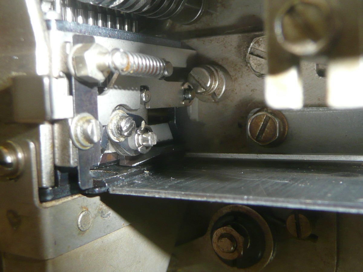
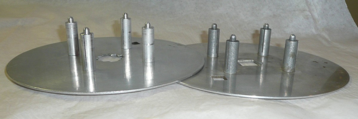
Bug 84: As noted on Apr. 7 our Fairchild Tape Winder came with a take-up reel sized for 7/8" wide paper tape, while the PDP-8 uses 1" tape. We also found out that Bunnell made this reel in a variety of widths, so we purchased aluminum stock to make the parts needed to change the reel width, while reusing the two aluminum disks that served as flanges on the two sides of the reel. The reel is held to the winder shaft by a set screw, and the reel snaps open, with the two halves held together by a ball-lock mechanism.
|
The difficult part of making the new posts was that the posts are slit to 1/8"
from the screwed on end. This slit is there so that the end of a piece of
paper tape can be tucked into the slit to start it winding. We had to defer
turning the un-slit end of the posts until after slitting, because we needed
excess length on that end to hold the posts while slitting.
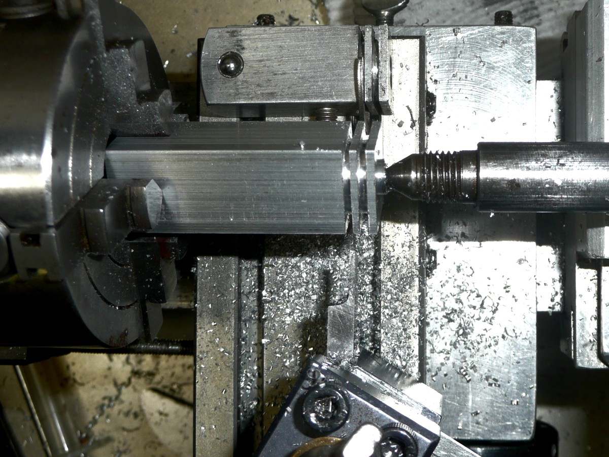
The slit post, however, was difficult to hold firmly in the lathe for
turning the end to length, drilling and tapping. We spoiled one post learning
this. The solution was to make a spacer that fit in the slit, allowing the
post to be tightly clamped.
|
After turning the hub end for end in the lathe, we turned the spherical end. We learned the hard way that we needed a tailstock center to support the end during this turning, ruining our first try by ripping it out of the headstock. The e-clip grooves weakened the clamped end of the hub enough that it was not securely clamped. We turned the bulk of the 1" diameter spherical surface first, leaving a spiggot for the tailstock center, then sawed off this spiggot without disturbing the workpiece in the lathe chuck. To turn the final portion of the spherical surface, we had to use very light cuts.
We spoiled another workpiece drilling the cross holes for the set screw and ball-lock mechanism. Our drill-press was too imprecise to keep these holes on center, so on our third try, we clamped the workpiece sideways in the 4-jaw lathe chuck to drill it.
The final challenge was the ball-lock mechanism. This
consists of two ball bearing balls with a spring between them. The balls were
held into the old hub assembly by swaging the ends of the cross-hole to a
slightly smaller dimension. In the photo of the old and new hubs, evidence
of this swaging is visible in the form of an indented ring around the end of
the ball visible in the side of the old hub. We used a hammer and punch
to drive the balls and spring out of the old hub. This damaged the spring,
so we replaced it with half of an old ballpoint pen spring before
swaging the assembly in place in the new hub.

|
To swage the ball-lock mechanism into the new hub, we turned a steel punch
to the diameter of the indent in the old hub. We also cut a conical hollow
in the center of the punch to it could center itself on the ball.
With the balls in place, we squeezed the punch into each side of the hub
using a vise. The result works perfectly, as can be seen in the photo
here of the comnplete assembly mounted on the Fairchild winder and being
used to wind up 1" wide paper tape.
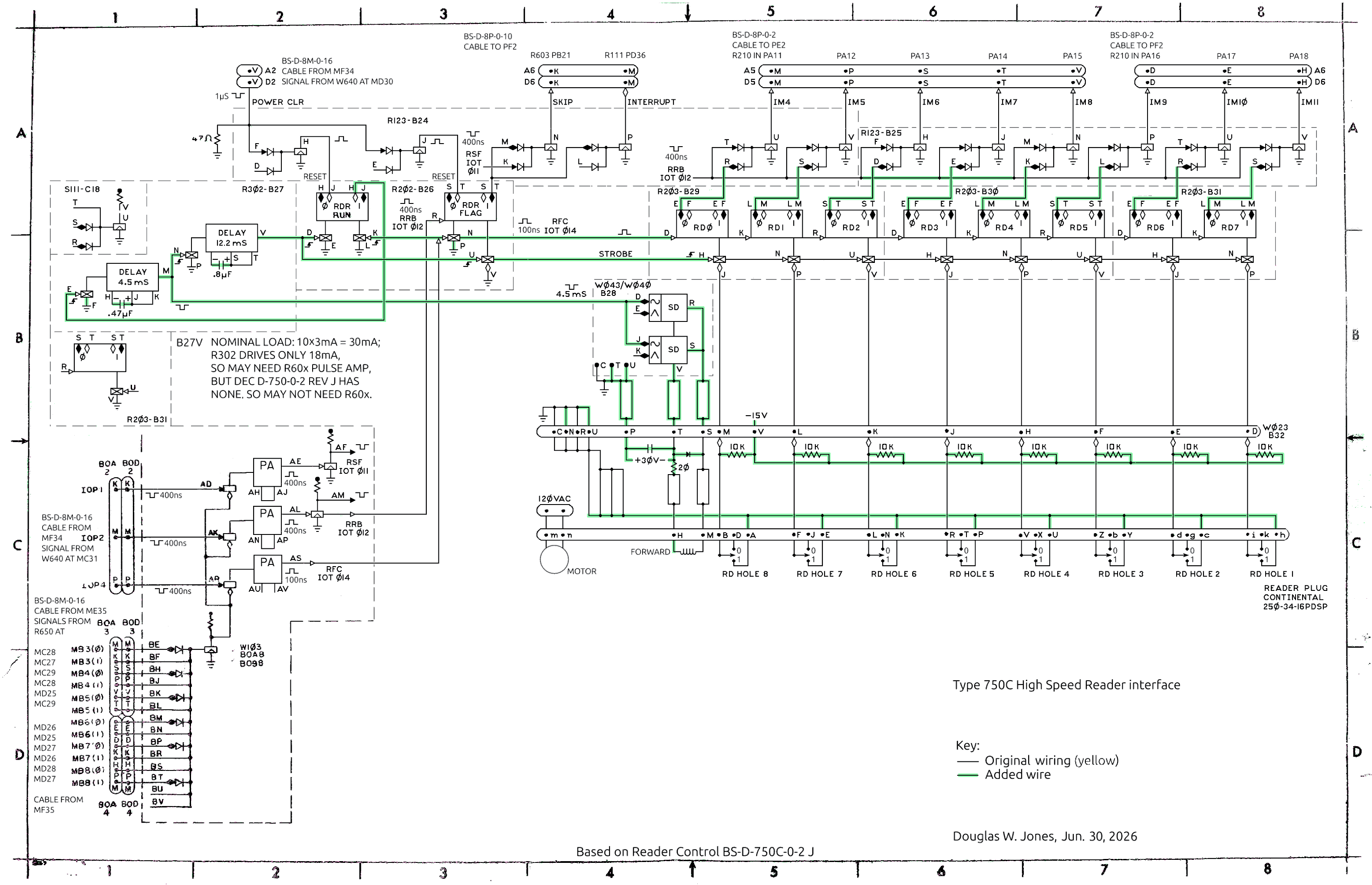
Bug 82: As noted on Mar. 5 the interface the psychology department built for the Tally 424 paper-tape reader is unnecessarily complex. On further study, we worked out the function of the chain of 4 one shots (2 R302 boards) the psychology department put in backplane slots D31 and D32. These one shots trigger a sequence of pulses that begins when an RFC instruction (IOT 014) sets the RDR-RUN flipflop.
|
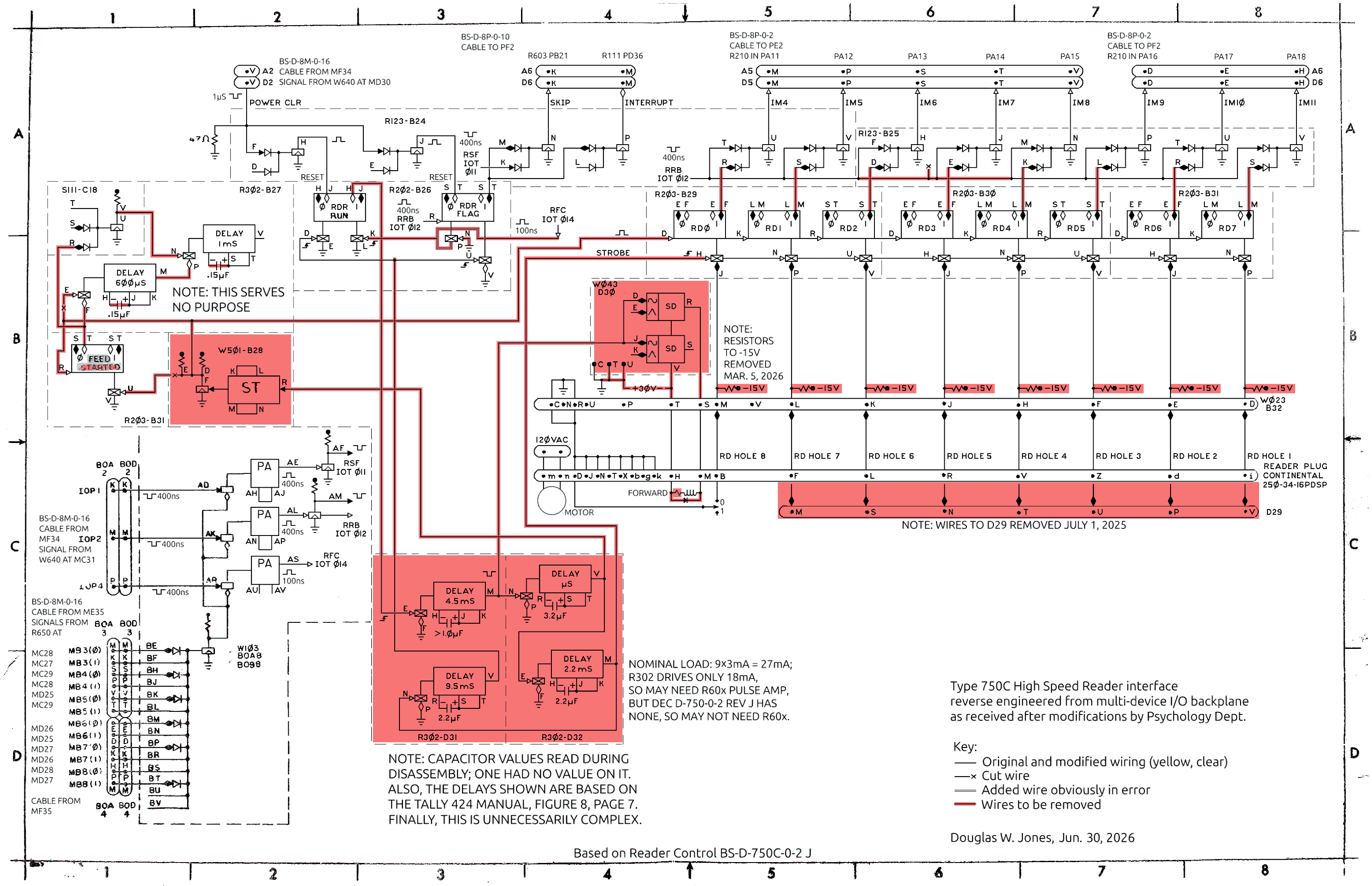
The schematic shown here is a further annotation of the one given on
Mar. 5,
with red highlighting on every wire and component that seems wrong to us.
This includes the unnecessary inversion of the data, a job we did by a
change in the cable wiring we assembled
Mar. 26.
The psychology department had already removed all the connections from outputs
of the two one-shots in slot B27, and they were using the
W501
board in slot B28, a
schmidt trigger
circuit as an expensive inverter that we no-longer need.
|
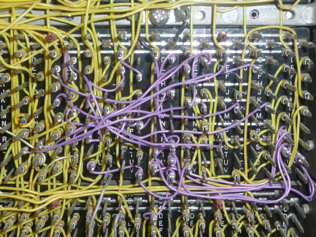
In total, we finished wiring changes in the data path through the interface and the wiring of the solenoid driver, leaving the bulk of the control wiring changes for later lab sessions.
|
|
This tuning job could be done in the final circuit, but it is much easier
to do this kind of tuning on the lab bench, so we began work breadboarding
our small backplane segment so that we can tune the one-shots on the bench
before moving the capacitors and circuit boards to the backplane. We suspect
DEC did the same thing during manufacturing. This would explain why all of
their timing capacitors are mounted on backplane pins using push-on clips.
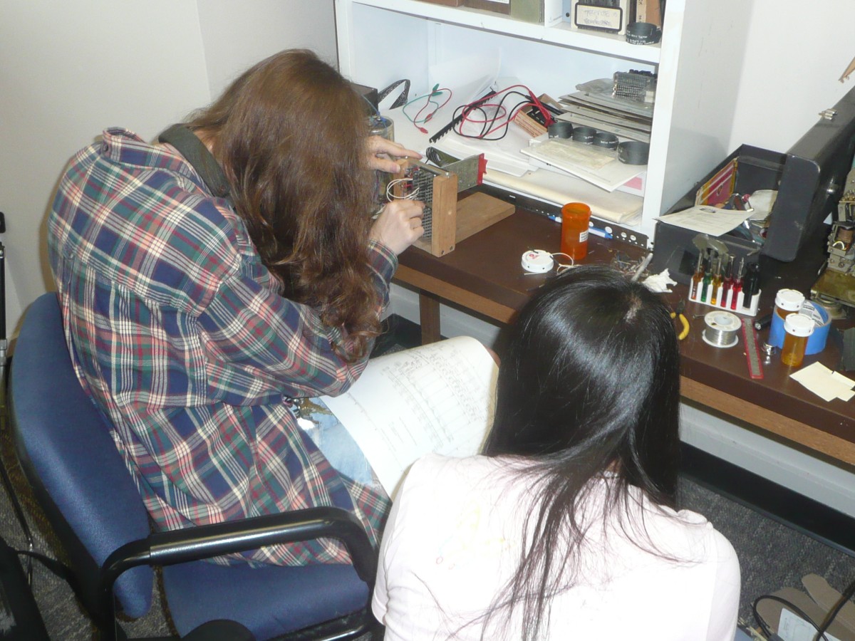
We will do the same thing. The photo here shows Magnolia Wallerich and Yihsun
Chao using push-on jumpers to wire the breadboard.

|
The original wires for this purpose were carelessly draped across the rack. We decided to include the new wires in the wiring harness for the rack power wiring. This harness is bundled with spiral-wrap nylon, so adding a new wire to the harness requires unwrapping, adding the wire, and then rewrapping. This is tedius and occasionally frustrating but not technical work.
|
Bug 89: In shortening the bus, we removed any terminators that might have been present. We found a number of resistor-capacitor pairs attached to the tape drive interface that we removed from the ADC rack on Feb. 21, 2018. Each RC pair was attached to two wire-wrap pins using cliop-on connectors, and the leads to and between components are insulated using brown insulation; this combination is one that we have come to recognized as DEC factory original, so we may relocate some of these to the current end of the bus.
We also disconnected the logic power connection between the Type 34D and ADC backplanes, leaving only the former connected to the power supplies in the back of the rack. These connections are done with connectors on the left side of each Type 1943 mounting panel making up the backplane. We pulled the lower ends of the +10V and -15V jumpers from the bottom mounting panel in the ADC backplane to the top panel in the Type 34D backplane, leaving the ground connection undisturbed.
Finally, we disconnected the -30V power line to the Type 750C interface so that our initial testing of this interface will not involve power to the reader's tape-advance solenoid or the solenoid drivers.
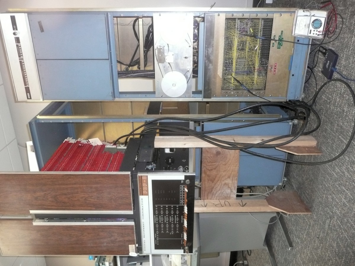
After making these disconnections, we connected the power cable from the computer rack to the ADC rack. This involves both 120V AC wires and wires carrying +10V ande -15V from the marginal check power supply. We also connected 5 of the 6 I/O bus cables from the CPU cabinet to their slots in the Type 34D backplane. We only connected the bus cables required for the Type 750C High-Speed Reader Interface, so the one cable used only for input to the CPU was omitted. As indicated on our annotated schematic posted on Mar. 5, only the following cables are required:
| PDP-8 | Type 750C | Use |
|---|---|---|
| MF34 | BA2 | IOP1, IOP2, IOP3 (operation), clear |
| ME35 | BA3 | Device address (high bits) |
| MF35 | BA4 | Device address (low bits) |
| PE2 | BA5 | Data in (high bits) |
| PF2 | BA6 | Data in (low bits), skip, interrupt |
Again, we found that someone had labeled the bus cables with the slot numbers at both ends, although there was a mistake in the labeling. Two cables had labels saying PE2. This was done using red pencil. After finding out which one ought to have been labeled PF2, we used a cotton swab soaked in plastic solvent cement to remove a stroke from the letter E so converting it to an F.
Note that all of our inter-rack connections were made with the side panels removed from the rack and the computer extended on its rack slides. We made no attempt to run the cables neatly nor to position them so that the racks could be properly closed. This connection between racks is intended to be temporary!
|
|
We then verified that the PWR CLEAR signal is inverted and delivered to the RDR RUN flipflop on Pin B26J of the backplane. It is, so we wrote a very small program to exercise the Type 750C interface:
          / program to issue an RFC pulse every 5.5 microseconds
2000 6014 LOOP,   RFC
2001 5200         JMP     LOOP
As expected this program caused an RFC pulse to be decoded on pin BA8S, the output of the devicel selector in the Type 750C interface. The schematic documents this as a 100nS pulse, but we saw a 400nS pulse. On exploring the backplane wiring, we found an uninsulated wire shorting pins B8AU to B8AV; this short changes the timing of the pulse amplifier so it delivers a longer pulse. On removing the wire, the pulse was shortened.
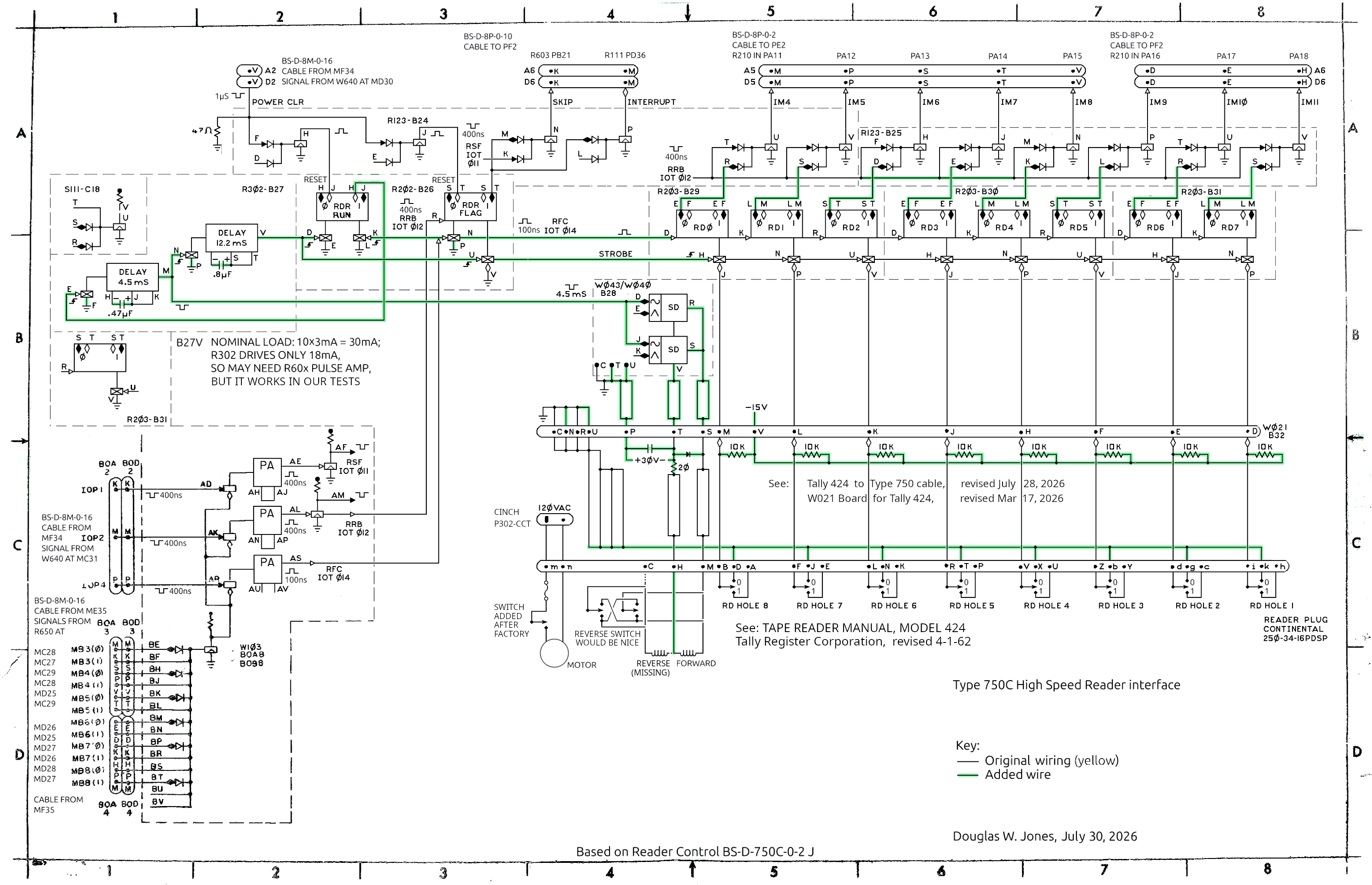
The expected behavior of the modified Type 750C interface is that, on receipt of an RFC pulse, RDR RUN flipflop will be set, triggering the chain of 2 R302 one-shots in backplane slot B27. At the end of 16.7mS, these one-shots should clear the RDR RUN flipflop awaiting another RFC pulse. We did not observe this behavior. Insead, the RDR RUN flipflop was set by the first RFC and remained set.
Bug 43 and Bug 82: Continuing the debugging work from July 17, we found that we had omitted another wire, the one grounding (pulling up) pin B27P, the level input to the second one shot on the R302 in slot B27 of the Type 750 backplane. Given that each of these one-shots had a diode-capacitor-diode and gate on its input, failing to ground this pin prevented the one-shot from being triggered. With this reapir, our test program (an infinite loop of RFC instructions) reliably produced 60 pulses per second to the solenoid driver.
Bug 79: When we connected the 30V power supply to the interface, we could hear the tape-advance solenoid buzzing at that rate, and when the tape-reader power switch is turned on, so the motor runs, the solenoid works the escapement and the capstan rotates.
We wrote a more ornate test program that included all of the IOT instructions that interact with the high-speed reader.
          / program to test the high-speed reader
2000 6014 LOOP,   RFC             / start read
2001 6011 POLL,   RSF             / polling loop waiting read
2002 5201         JMP     POLL
2003 7200         CLA             / prepare to load result
2004 6012         RRB             / load result
2005 7402         HLT
2006 5200         JMP     LOOP    / continue
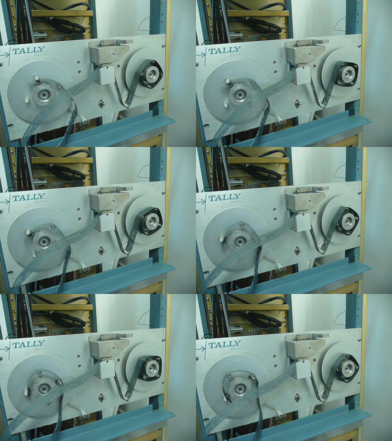
As written, this program halts after each character is read, showing the data on the accumulator lights until the continue switch on the front panel is tapped. This worked, with the tape stepping one character forward for each tap on continue. Replacing the HLT with a no-op makes the program read data at full speed.
|
Aside from the data inversion, the program worked. We could read tape one byte at a time, and we could read tape at full speed. We were a bit annoyed, though, that the tape feeds from right to left. This seems unintuitive, but the Tally manual, Section 3.1 defines forward as counter-clockwise capstan rotation, forcing right-to-left to be forward. Unfortunately, this requires the tape to be mounted upside-down, that is, with the side that is up on a Teletype facing down. The up-side, of course, is traditionally printed with the word TOP and arrows to show the direciton of tape motion. Our Tally reader has no feed solenoid for reverse feeding, but we could cannibalize our spare reader for one to fix this problem.
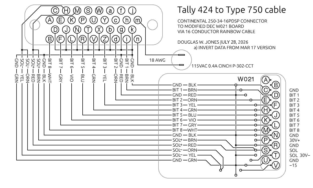
The data inversion was obviously a mistake. We suspect that two factors contributed to this: First, DEC's archaic logic notation, with solid arrows indicating negative logic and hollow arrows indicating positive logic is difficult for modern readers. Second, when we reverse-engineered the poorly constructed interface the Psychology department had built on June 13, 2014 we found a cable that did not match the corresponding backplane slot, so we made inferences that may have been wrong when we designed our cable on March 20.
Bug 12: There are several possible solutions to this inversion problem. We reject one, changing the type 750 controller to invert the data. The Psychology department did this, but on July 7, we decided to revert this change to make our logic conform to the original DEC design given in drawing BS D-750C-0-2 revision J. The least invasive option is to rewire the cable connector that plugs into the Tally reader. We designed our cable on Mar 20 and built it on Mar 26. The required change involves moving a row of grounded pins on the connector.
|
To test the reader with this change, we wrote a little program on the PDP-8 to punch a tape on the Teletype containing all 8-bit codes from 0 to 255 in a repeating cycle. We then cut out a full cycle plus 10 extra codes at each end so we could splice the tape into a loop. We followed the tape splicing instructions in Section 6.0 of the Tally 424 Tape Reader Manual, except that we used a glue-stick instead of rubber cement to make the splice, and we tapered the cut ends of the tape by cutting at a shallow angle with a razor instead of using sandpaper.
Bug 87 and Bug 88: Testing with this tape made it clear that we do have intermittent read errors. In addition, during our tests, the reader stalled twice. During the stalls the tape-advance solenoid continued to tick, but the escapement teeth stopped advancing. Furthermore, during one stall, we observed that the escapement teeth had stopped before the engaged with the lever from the solenoid.
We tried cleaning the read head on the tape reader. The head has wire contacts that move up and down between metal fingers, with a tiny gap, as shown in Figure 7 in Section 2.2 of the Tally 424 Tape Reader Manual. We found it very difficult to attempt to clean these contacts, and our effort had no apparent effect. We will have to try following the read-head service procedures documented in Section 5.2 of the Tally 424 Tape Reader Manual.
As we noted on July 21, it would be nice to be able to read tape with the supply reel on the left and the take-up reel on the right. To do this, we would need to replace the reverse solenoid in the reader with one that actually has a coil. We extracted a solenoid from our spare reader and found that it is not interchangable with our reader.
Section 3.6 of the Tally 424 Tape Reader Manual shows that Tally offered readers to operate at 24V or 48V. Ours is a 24V reader with a 50Ω (nominal 70Ω) coil while our spare reader appears to be a 48V reader with 200Ω (nominal 220Ω) coils. The resistances given here are ones we measured, while the nominal values are quoted from the manual. We may want to investigate making or modifying a coil for our reverse solenoid. The required change involves moving a row of grounded pins on the connector.
Bug 82: A lingering concern we had with the Tally reader was whether the read errors might be electronic errors in the Type 750 interface and not mechanical errors in the Tally reader. To determine this, we wrote the following test program:
          / program to test the high-speed reader
2000 6014 LOOP,   RFC             / start read
2001 6011 POLL,   RSF             / polling loop waiting read
2002 5201         JMP     POLL
2003 7200         CLA             / prepare to load result
2004 6012         RRB             / load result
2005 7402 DEL1,   ISZ     DELAY   / delay loop
2006 5200         JMP     DEL2    / -- use DEL1 here for shorter delay
2007 5200         JMP     LOOP    / continue
2010 5212 DEL2,   JMP     DEL3
2012 5205 DEL3,   JMP     DEL1    / padding for delay loop body
This program runs the tape reader at about 2/3 of the 60 character per second top speed. With this program running but the motor turned off, we could work the mechanism by hand to advance our test tape.
|
For our second test, we positioned the tape so it read 11111111, and then
selectively grounded each of the data pins where they come into the backplane.
These are pins B32D, B32E, B32F, B32H, B32J, B32K, B32L, and B32M, from least
to most significant bit. We got the expected values in response, ranging from
11111110 through 11111101 to 01111111. Moving the tape one space on our
test tape gave 00000000.
|
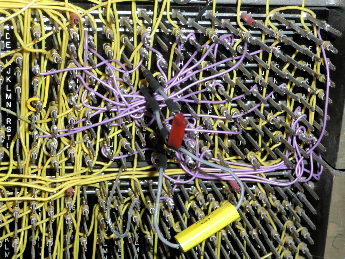
Therefore, we declare this version of our Type 750C interface to be completed. We note, however, that we could divide the load on the strobe line by using the leading edge on the RDR FLAG flip-flop output, pin B24S, to strobe 5 of the reader data flipflops. The photo here, unlike the one given on July 7, includes the timing capacitors attached to the backplane with push-on connectors.
We have attached a backplane module utilization list of our modified Type 750C interface. This map corresponds to the schematic given above.
Bug 89:
We had noted on
July 17
that our shortened I/O bus is unterminated.
On close investigation of the
9-track tape drive interface, we found that
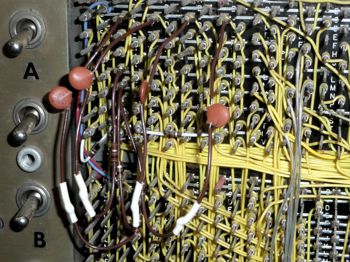
the psychology department had terminate all 12 memory buffer lines on the
bus. 4 of these lines were terminated using push-on clip RC networks typical
of DEC factory-original mounting of components on the backplane, while the
others were wire-wrapped to backplane pins. We assume this was done by the
psychology department. The terminators each had a .01μF capacitor
in series with a 100Ω resistor.
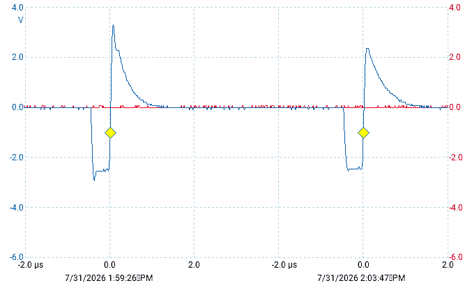
|
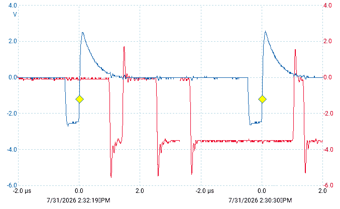
Looking at the I/O bus, these 4 pulses appear to be the only ones that might
need termination. In fact, the maintenance manual advises against
terminating bus lines.
See Chapter 6, subsection on Loading and Driving Considerations, at the top
of page 6-3 of the
Maintenance Manual.
|
|
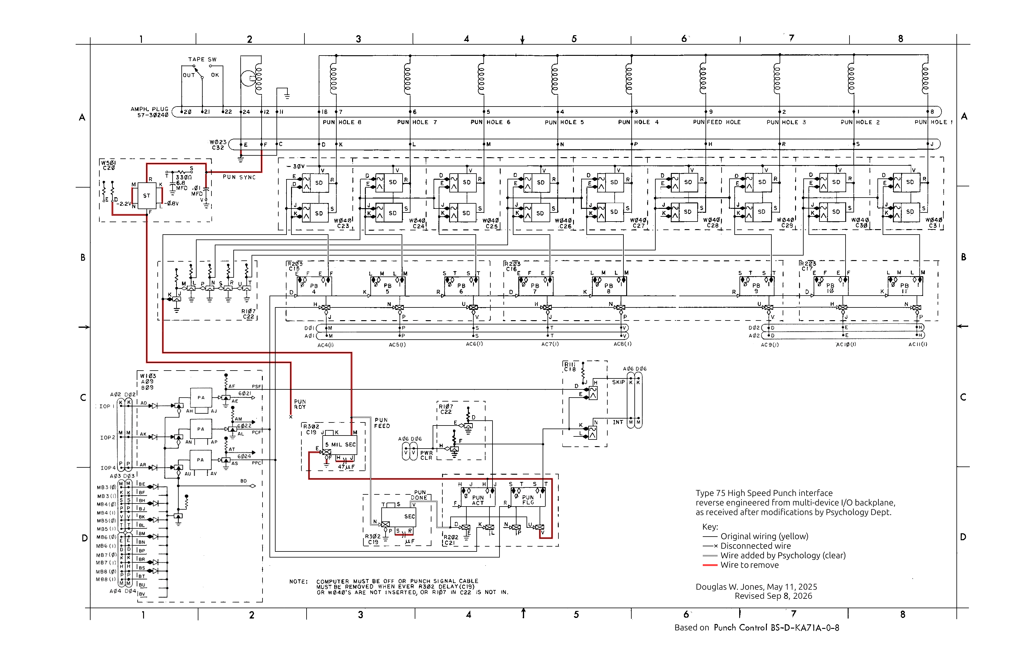
Bug 72: We went back to the drawings produced on May 21, 2025, and set to work producing woking drawings for modifying the Type 75E high speed punch interface to support the Teletype BRPE punch. We had produced two drawings, one of the interface as we found it, and one as we beleived we needed to modify it to support the BRPE punch.
|
Note that, because of the wire-wrap construction of the backplane, there were occasions when there were two wires wrapped on the same pin. If the upper wrap on that pin needed to be removed, the lower wrap could remain undisturbed, but if the lower wrap needed to be removed, the upper wrap had to be removed as well. In these cases, we red-lined the additional wires on our working drawing. The drawing presented here includes red-lines on those additional wires.
As we were working on this, we realized that the wiring, as found, was pushing an unrasonable amount of current through the cable connectors between the BRPE punch and the Type 75 interface. Each solenoid in the punch is documented as drawing 1A during each 5.0mS punch cycle. At the rated 110 cycles per second, the average current for one solenoid will be 0.55A when punching a series of ones. With 9 solenoids in parallel, the maximum solenoid current is 9.0A, and the average can be as high as 5.5A when punching a series of rubouts (all ones).
All of this current flows through pin 18 on the Amphenol 57-30260 Micro-Ribbon connector, and the data sheet for that connector family states that the maximum current per contact is 5.0A. Teletype ought to have wired at least 2 contacts in parallel to handle this current, but as our reverse-engineering work on Apr. 17, 2025 showed, they did not.
At the other end of the cable, DEC's drawings show this entire current flowing through pin D of the W023 board in backplane slot C32 of the Type 75 interface. We have been unable to find specifications for the maximum current DEC allowed on single backplane pins, but we can draw inferences from the specifications for the W040 and W043 solenoid drivers. The W040 contains 2 drivers with an aggregate capacity of 1.2A; this current flows to ground through pin C when both drivers are on. In the case of the otherwise compatable W043, the two drifvers have an aggregate capacity of 4.0A, and DEC used 3 ground pins "to limit the current through each connector pin to safe levels." This implies that one pin could not handle 4.0A. The datasheet for the comparable ECAC 346/396 connectors shows a similar contact spacing and gives a 3.0A capacity per pin.
We believe that it would be prudent to work in terms of these limits.
Teletype's schematic for the BRPE punch is given in Figure 6-10 of
Teletype Bulletin 215B from 1960.
This shows no use being made of pins 13 to 17 or pin 19.
DEC's Drawing BS-D-KA71A-0-8
for the Type 75 Punch Control on the PDP-7, given on page
6-144 of the
PDP-7 Maintenance Manual,
shows that DEC added a remote on-off control to some BRPE punches that
involved adding a small circuit board inside the punch housing pins 13 and 14
on the Amphenol connector on the back of the punch.
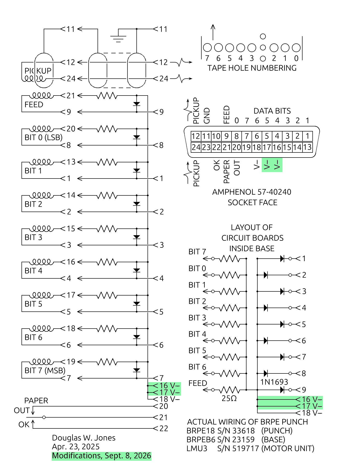
|
We are a bit puzzled why Teletype's engineers did not do something similar. We suspect that the reason is that the majority of all BRPE punches sold were for 5-chanel data (used with the Baudot code in military and wire-service applications). The Baudot code deliberately minimises the number of holes punched, with common letters like E, T and A all coded with just one punch each. Only very uncommon letters use more than 3 out of 5 punches. In addition, the BRPE manual makes it clear that the punch was designed in the vacuum tube era, with low-current high-voltage solenoids. Only later did they move to high-current low-voltage solenoids for use with transistorized equipment.
Similarly, we wonder why DEC's Type 75 Punch Control, both as we found ours wired and as the PDP-7 maintenance manual documents, used only one pin for the combined current to all 9 solenoids. They used the W040 driver, so they should have been aware of the current limits per pin on their backplane.
Finally, we note that the backplane wiring is all done with
24AWG wire.
The wire tables we consulted suggest that the maximum current through a single
strand of 24AWG wire should be limited to from 2A to 3A, depending on the
amount of heating that can be tolerated. Clearly, just as we need multiple
connector pins, parallel wires from these pins should be used.
| |||
|
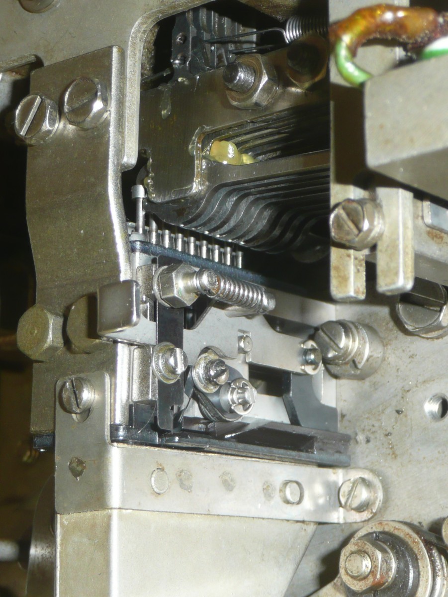
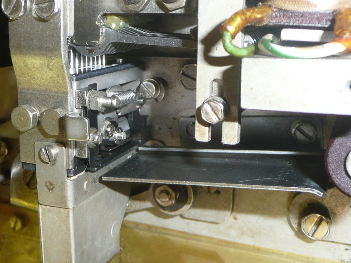
The adjustable punch block has a mechanism on its right side that are not
present on the standard blocks. These allow the block to be switched between
11/16" and 1" tape by the press of a button. The complexity of this adjustment
mechanism is apparent in the drawings in the parts list cited above, where
6 additional parts are shown screwed into the side of the punch block.
The photo of the installed block given here shows this complexity.
|
We will have to cut off about 1/16"
from the right end of the tape guide to resolve this, and we will need to
add a 0.049" spacer to mount this guide to make it correctly align 1" tape.

|
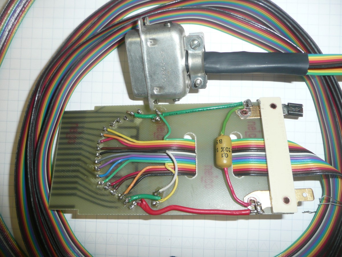
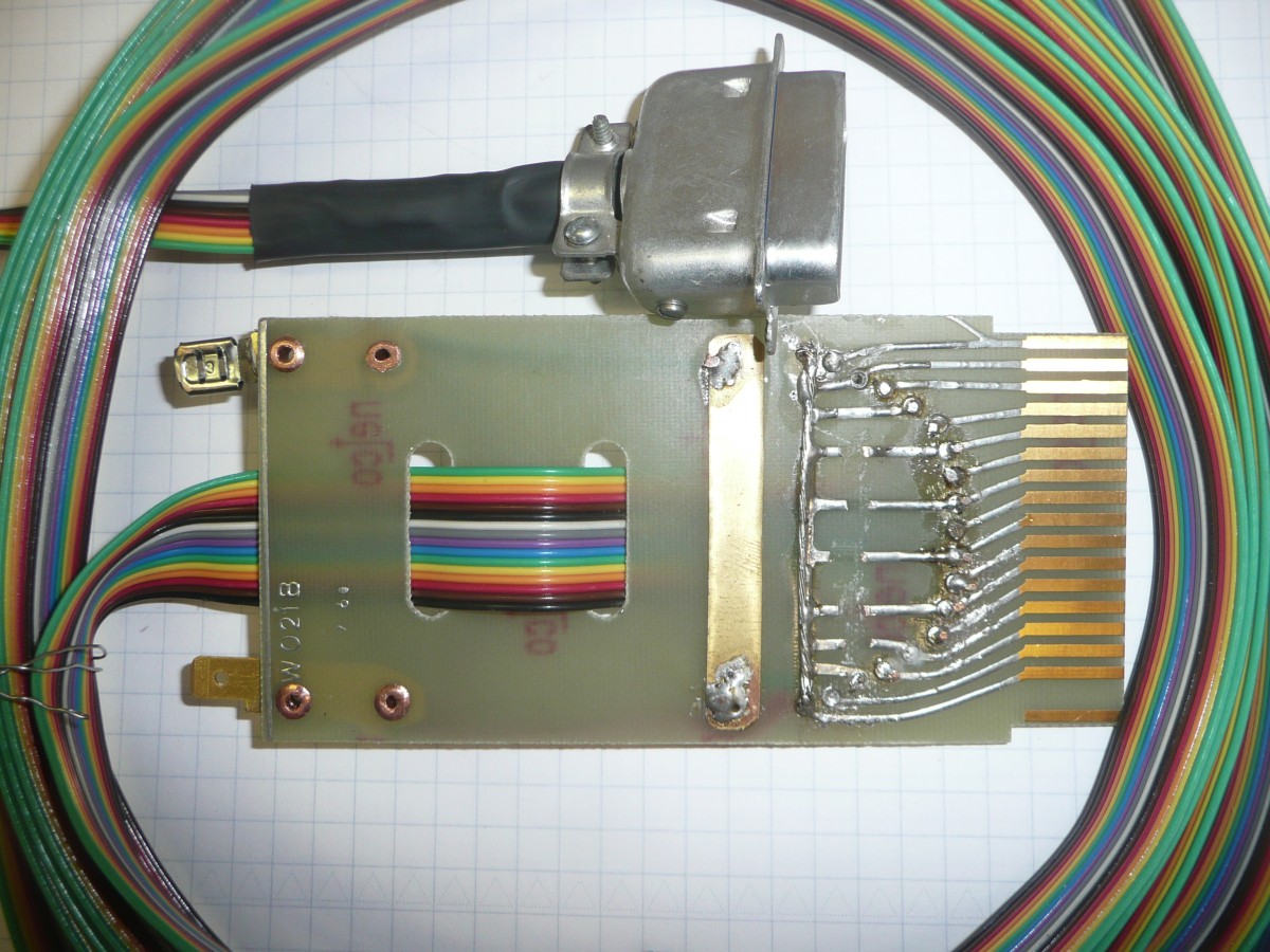
As with our cable between the
Type 750C
interface and the
Tally 424
paper-tape reader, we opted to bring the 30V power in to the interface through
the same backplane connector used for the cable to the device. Thus, power
flows from the positive side of the 30V supply to the ground connection on
this board to the solenoid drivers, from there back through this board to the
9 solenoids in the BRPE punch, and from there back to this board and back
to the negative side of the supply. Given that the peak current on the 30V
supply is 9A during each punch cycle punching a rubout (all ones) on the
tape, we used pins T and U as auxiliary ground pins, reinforced the ground
trace on the board by soldering a wire to it along its length, and added a
brass bus strip to the board for the negative side of the supply.
|
|
| |||
| |||
|
The tape guide we have was made for use with 6-channel 7/8" wide tape with an advanced sprocket hole, the standard tape format used for input to linotype machines. The techniucal manual for the BRPE punch, Teletype Bulletin 215B Figure 2, Section 592-802-100TC, page 3 (July 1969), states that the sprocket holes in this tape format are 0.441" in from the guiding edge, while for 8-channel 1" tape, the sprocket holes are 0.392" from the guiding edge. The difference is 0.049", the thickness of the shim needed behind our tape guide to make it work with 1" tape.
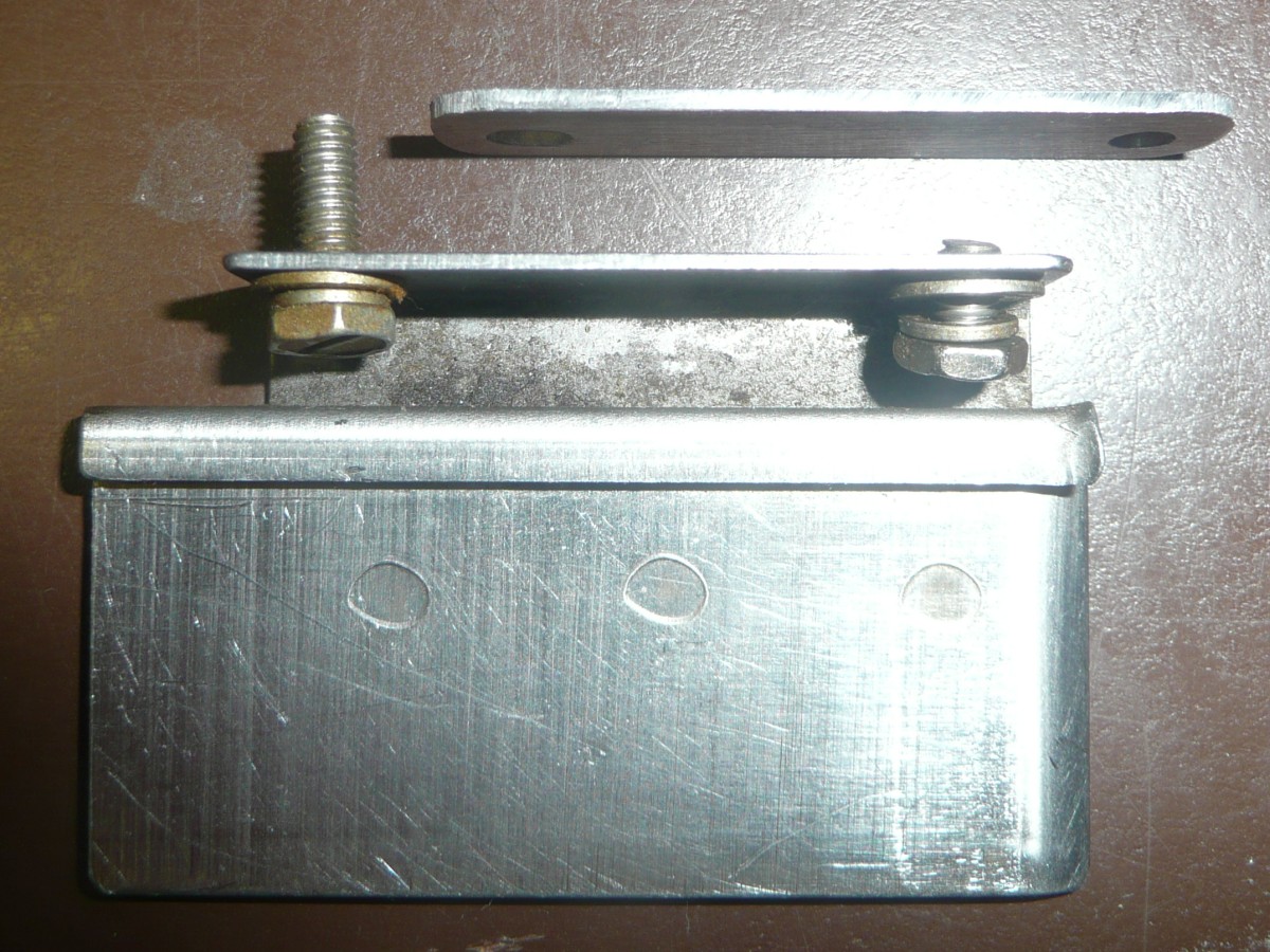
the BRPE parts list, Teletype Bulletin 1154B (June 1966), shows the use of a spacer, part 170766, to shim the tape guide to the correct position. We used the drawing in the parts list as a hint and made a steel spacer approximately .049" thick before we re-mounted our shortened tape guide.
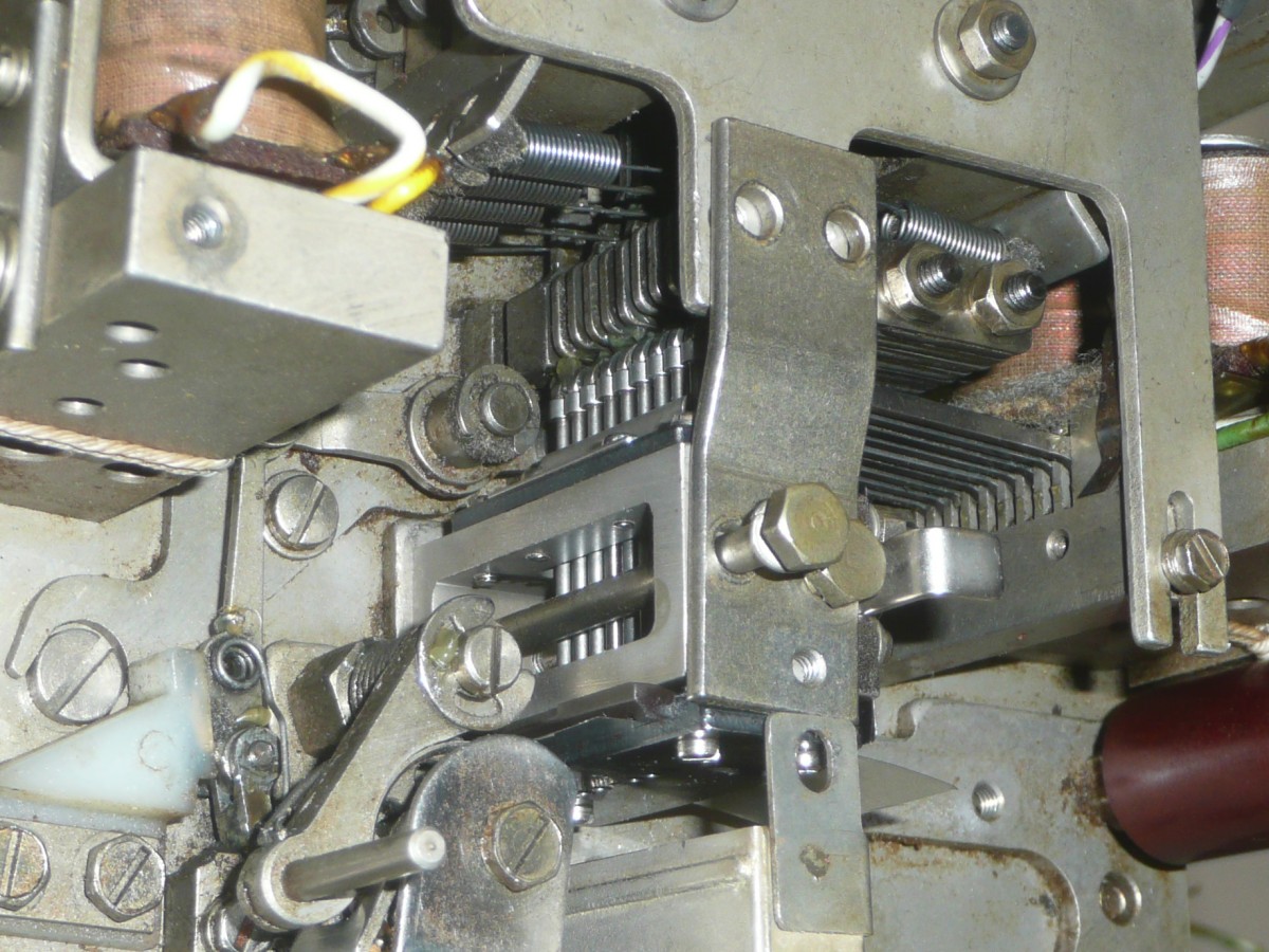
The screws Teletype used to mount the tape guide were so short that they could barely grip the tapped threads behind the spacer, so we salvaged longer screws from our second BRPE punch, our parts-donor machine. The photo here shows the old and new screws with the tape guide and spacer. Note that the screws we salvaged are longer than we need; are long enough to accomodate the thicker spacer that would be required if we were using narrow 5-channel tape.
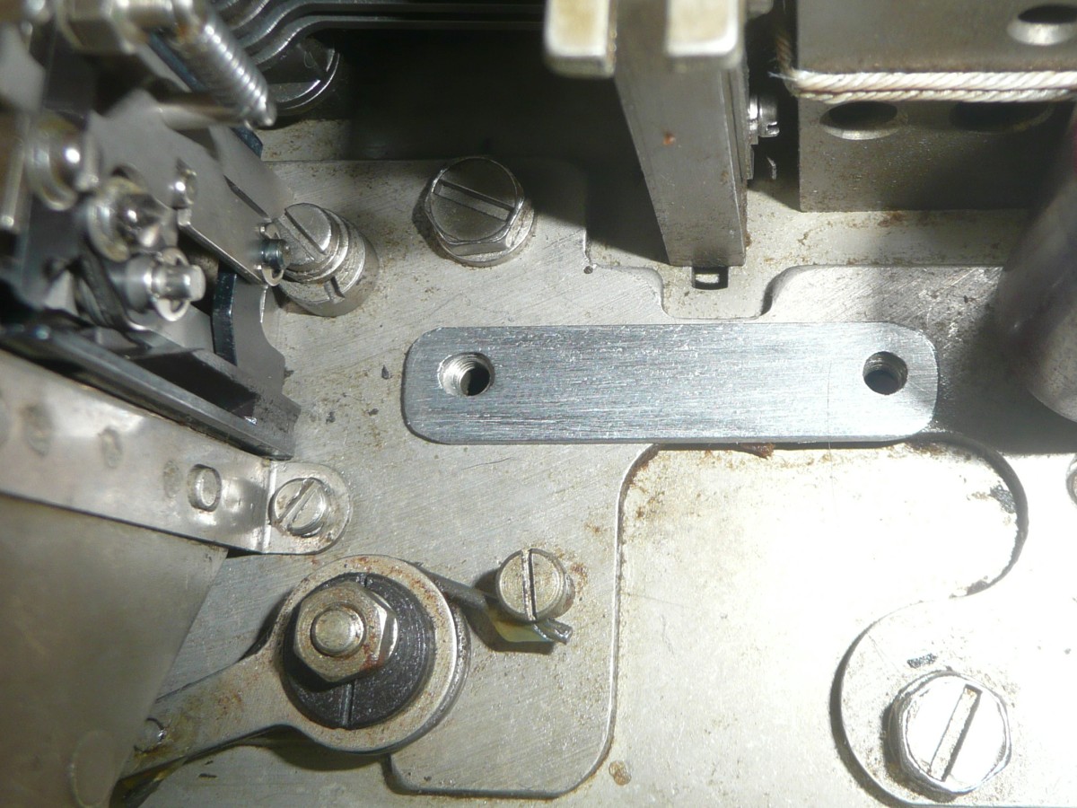
The final photo here shows the tape guide installed with just a small amount of clearance between the guide and the input slot in the punch block. When we tried feeding tape, we did not notice that the guide is a little low; that will be easy to correct and had no effect. We believe that, with the guide installed we have completed the job of combining our 2 6-bit BRPE punches to make one 8-bit punch (plus the cannibalized hulk of the other).
When we tried punching tape (just the
sprocket holes), we had serious difficulty. The sprocket holes were punched
so closely that the sprocket teeth tore the tape. There are elaborate
instructions in the techniucal manual for the BRPE punch,
Teletype Bulletin 215B
paragraphs 2.11 - 2.14, Section 592-802-700TC, pages 13 - 16 (March 1971),
for adjusting the feed holes so that there are
"ten to the inch." We will need to go through this carefully, along with
checking all of the other adjustments in the manual, creating
Bug 90.
Bug 91. We began work on rewiring the Type 75 high-speed paper-tape punch interface so it will work with the BRPE punch. First, we prepared a revision of the plan we presented on May 21, 2025, taking into account the observations we made about the high current flowing through some of the connections on Sep 8 and our subsequent revisions to the cable design given on Sep 22.
All wirwes to be added to the interface are shown highlighted in green in this schematic. Note that the schematic shows doubled wiring from the pins on backplane slot C32. This is the cable to the BRPE punch. Pins C, F and U are ground connections carrying the full current from the positive side of the 30V supply, while pins D and V carry the flyback pulses to the negative side of the 30V supply whenever a solenoid driver cuts off. In following this schematic, we took care to distribute these wires along the ground and -30V bus bars serving backplane slots C23 to C31, the slots occupied by solenoid drivers.
Another refinement we made was to use a twisted pair to connect
the input to the Schmidt trigger in slow C20 to pins E and F on slot C32.
These wires carry the sync pulse from the magneto in the BRPE punch. DEC's
punch control schematic that we used as a starting point in our
reverse engineering effort simply suggested grounding one of the lines
from the magneto at slot C32, a move that would greatly increase the
possibility of injecting noise into the sync pulse from crosstalk with the
high-current solenoid pulses.