
The University of Iowa's DEC PDP-8Restoration Log
Part of
the UI-8 pages
|
The University of Iowa's DEC PDP-8Restoration Log
Part of
the UI-8 pages
|
This is a chronological log of the progress restoring the University of Iowa's PDP-8 computer. Entries are added at the end as work progresses. Click on any thumbnail image to see full-sized image.
|
|
| Power supply dummy load | |
|---|---|
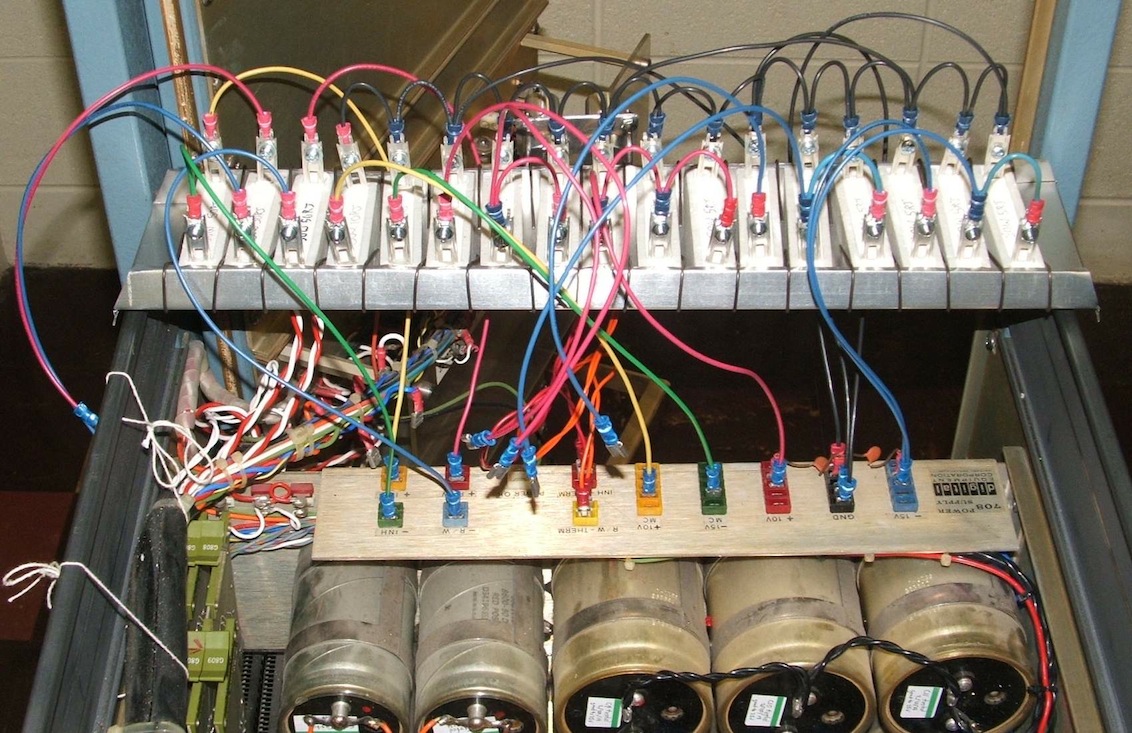
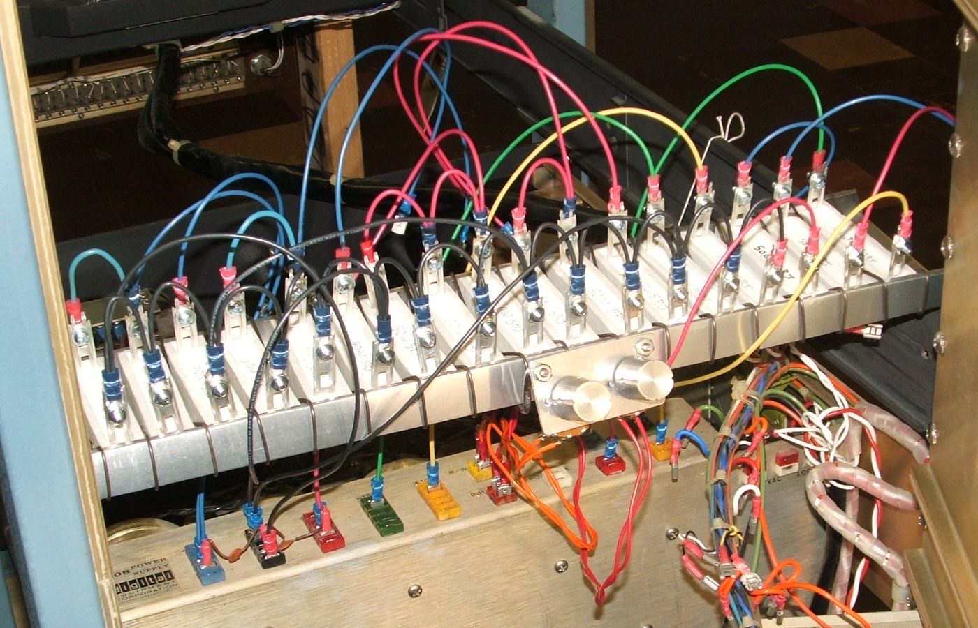
The primary loads for the -15V and +10V supplies are banks of 5Ω resistors. For the -15V supply, each resistor should draw 3A and dissapate 45 watts, for the +10 supply, each should draw 2A and dissapate 20 watts. Each bank has 6 resistors, a group of 3, a group of 2 and a singleton, allowing any combination of from 1 to 6 resistors to be used as a load on each supply.
We included two 10Ω for the marginal check supply (one would have sufficed, but to avoid wear on the faston connectors, we used two); at the maximum marginal check voltage of around 20V, this will draw 2A at 40W, which is the maximum rated output of the marginal check supply.
We used 50Ω resistors for the Inhibit and Read/Write supplies. These have maximum outputs of around 40V, at which point these resistors will draw under 1A at under 4OW. A spare 50Ω resistor was included in order to allow heavier loading on the Inhibit supply, since it is rated at 2A.
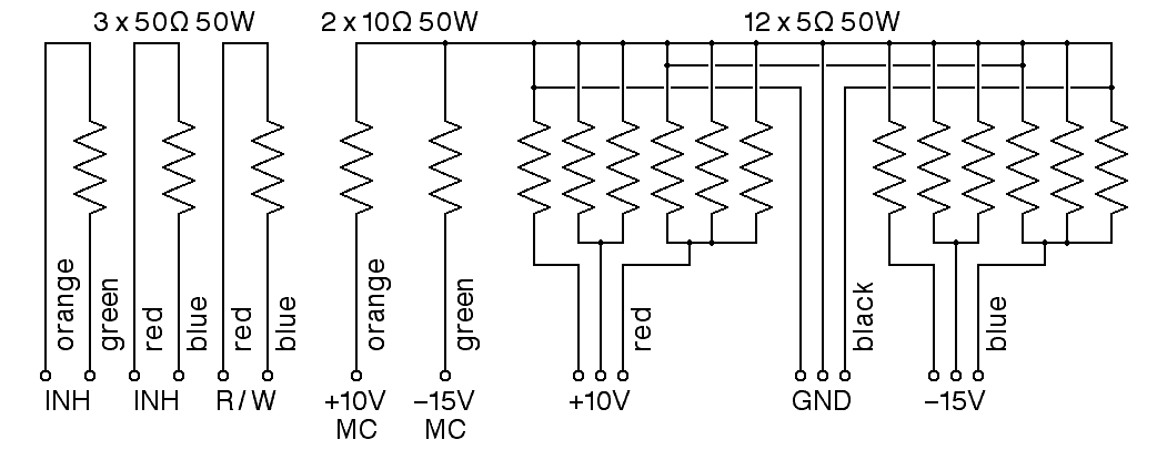
I made a point of wiring the resistors with wires that matched the color of the corresponding supply output connection point, to minimize the likelihood of wiring errors (but we had no orange, so we used yellow).
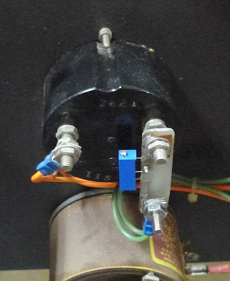
We added an outrigger to the dummy loads containing two 500Ω potentiometers so that we could test the linear regulation of the Inhibit and Read/Write supplies. Each pot can substitute for the thermistor that normally controls the regulated supply.
We started power testing after setting up the dummy loads with just three 5Ω resistors across the -15V and +10V supplies, and with the marginal check supply variac set to zero volts. For this test, we substituted a jumper for the on-off key switch on the front panel. Before plugging in the machine, we used an ohm meter to verify that there was no AC power path through the supply with the main circuit breaker in the off position, and that there is AC continuity with the breaker on. With those preliminaries out of the way, here are our first test results:
At this point, we stopped the test. The 3 active load resistors across the +15 supply were smoking. On closer inspection, the smoke came from the slightly oily soft iron wire we used to separate the resistors from each other. The resistor data sheet says that at 50W, these resistors should run at over 200C above the surrounding air temperature (this is above the melting point of tin-lead solder; the two-inch long legs on these resistors serve to isolate the hot resistor body from any solder joints). Smoke is not surprising in this context. We need to test the ripple on the output of each of the main supplies as a function of current, and we need to test the regulated supplies.
By the end of the testing, the total-hours meter had advanced from 26879.0 to 26879.1 -- about 6 minutes of running time.
Bug 33: The output of the main -15V supply was tested with varying numbers of 5Ω resistors in parallel across the load. The +10V supply was loaded with 3 parallel resistors (drawing approximately 6A) during this test. The power was turned off whenever the load was changed (by pulling and inserting Faston connectors). There was no ripple voltage measureable with the VOM used to make the measurements - the VOM was tested on a 1V AC source to verify that it did work.
| Resistors | Current | Voltage |
|---|---|---|
| 1 | ~3A | -14.7V |
| 2 | ~6A | -14.5V |
| 3 | ~9A | -14.5V |
| 4 | ~12A | -14.5V |
| 5 | ~15A | -14.4V |
The output of the main +10V supply was tested with varying numbers of 5Ω resistors in parallel across the load. The -15V supply was loaded with 3 parallel resistors (drawing approximately 9A) during this test. Again, there was no ripple voltage measureable with a VOM.
| Resistors | Current | Voltage |
|---|---|---|
| 1 | ~2A | 10.1V |
| 2 | ~4A | 10.0V |
| 3 | ~6A | 10.0V |
| 4 | ~8A | 9.7V |
| 5 | ~10A | 9.6V |
The Marginal Check supply was tested while loaded with a 10Ω resistor. During this test, both of the main supplies were loaded with 3 parallel resistors each, so the +10V supply was loaded at approximately 6A and the -15V supply at 9A.
| Current | Voltage (VOM) | Voltage (panel) |
|---|---|---|
| ~0.5A | 5.0V | 5.5V |
| ~1.0A | 10.0V | 11.2V |
| ~1.5A | 15.0V | 16.5V |
Bug 35: This verifies that the Marginal Check panel meter is showing almost exactly 10% higher than the actual voltage. David Gesswein had a similar problem that he solved by adding an external resistor in series with the panel meter. We should probably do something similar.
Bug 36: Finally, with the main supplies loaded, we noted that there is no voltage present on the Inhibit and Read/Write outputs. When we cycle the power, there is no evidence that the relay to connect these outputs operates. The input to these supplies, measured across the filter capacitors, is a solid +60V, so the problem must be in the electronics.
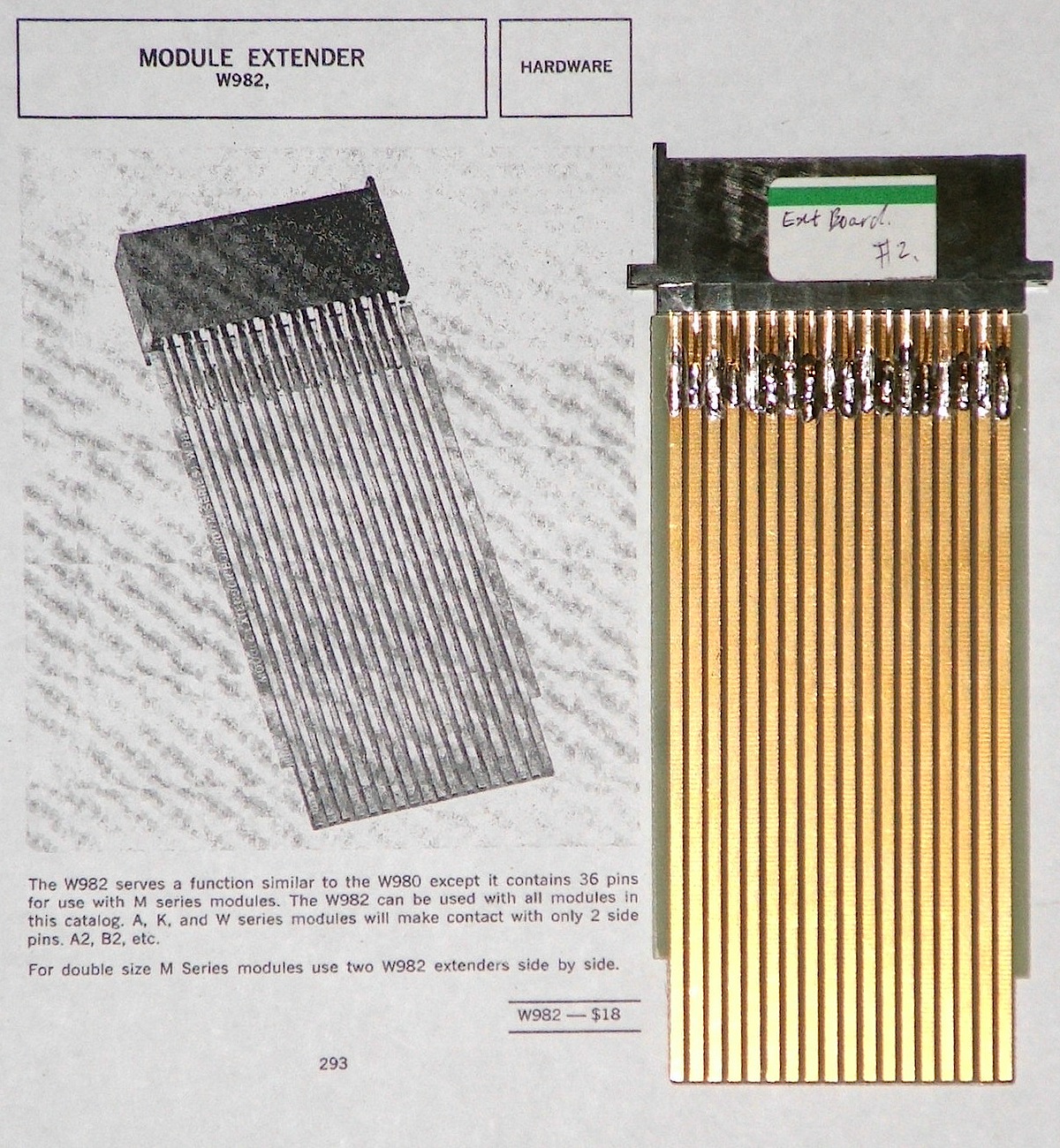
Bug 37: We will need an extender card to get access to the regulator circuit boards.
By the end of the testing, the total-hours meter had advanced from 26879.1 to 26879.2 -- about 6 minutes of running time.
|
| Trimmer Mounting |
|---|
I checked my VOM's voltmeter calibration using a regulated 19V power supply,
then adjusted the trimmer so that the meter read 15V when the marginal check
supply was delivering 15V at 1.5A to a load resistor. In retrospect, this
might not be the right way to calibrate it. We should go back to this and
measure the voltage drop due to the internal wiring in the power supply between
the meter back and the dummy load. Only if this drop is negligable should we
accept the current calibration. Otherwise, we should recalibrate while the
supply is running at about half its rated output in order to account for
the typical voltage drop in the wiring.
|
| H807 Connectors |
|---|
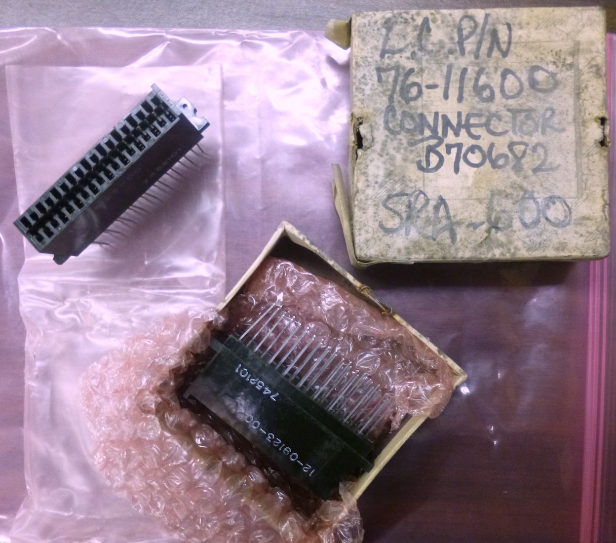
We were going to buy the 6-DE-11-C from Douglas Electrnics when we came
across a pair of reasonably priced H807 Connector Blocks on eBay.
These were advertised as NOS (new old stock) and indeed, when they arrived,
they were very-old stock. I have never seen so much mildew on a cardboard
box. The boxes may have been toxic, but fortunately, the connectors
themselves seem to be in fine condition.
|
|
| Power Supply | |
|---|---|
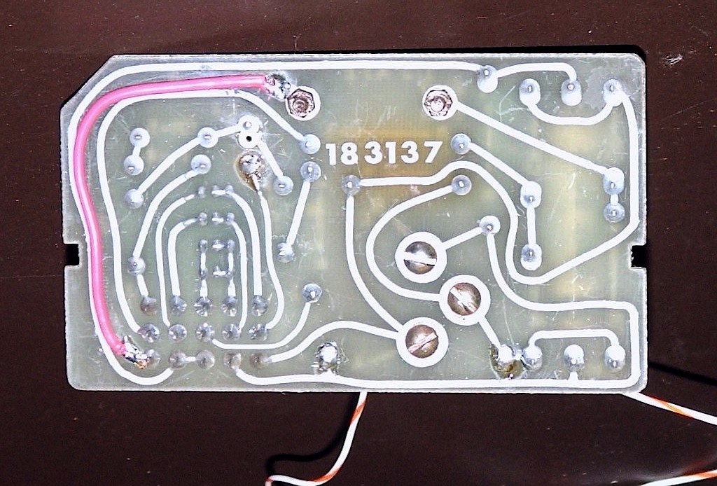
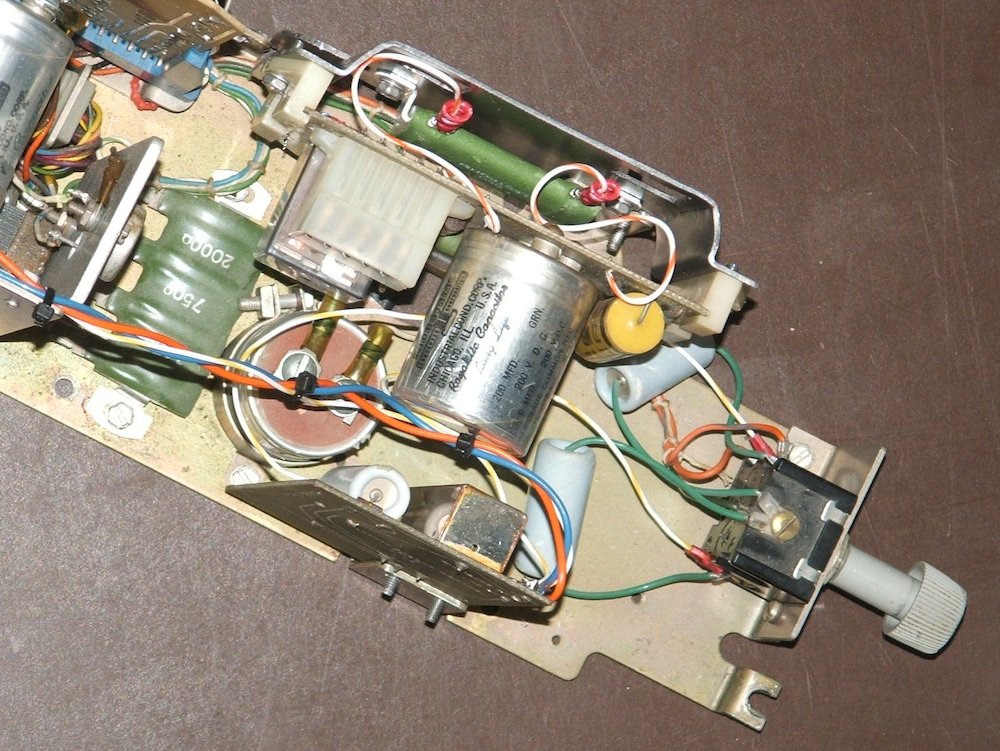
We managed to locate a power supply on eBay. On receipt, we found that one trace on the power supply board was almost entirely gone. Curiously, this is the same trace as Tommie Mademark found to be burnt out in his Teletype. (See his blog posting Fixing the paper tape reader on my Teletype ASR 33.) His circuit board is of much newer vintage than ours, and on his board, the circuit trace only required a very short bit of large gauge wire to bridge the gap. We will require much more, as the entire length of the trace is almost entirely gone.
Bug 10:
Meanwhile, we have begun to work on reforming the capacitors in the
Type 779 power supply. We begin with capacitors C1 to C3, wired across
the +15V output driven by T1 (the one with the +10 and -15 outputs).
As with our previous reforming efforts, we unsoldered one side of each of
the 35,000µF 25V capacitors
and then tack-soldered a 510Ω series resistor to it.
We followed the same procedure documented in the log entry for
Feb. 11 for the main
PDP-8 power supply, turning up the voltage while monitoring the current,
and keeping the current well under 1mA.
| |
| The Repair | |
|---|---|
Bug 10:
By the end of the day, the capacitors were sitting at 25V, where we will
leave them for a while before testing.
|
|
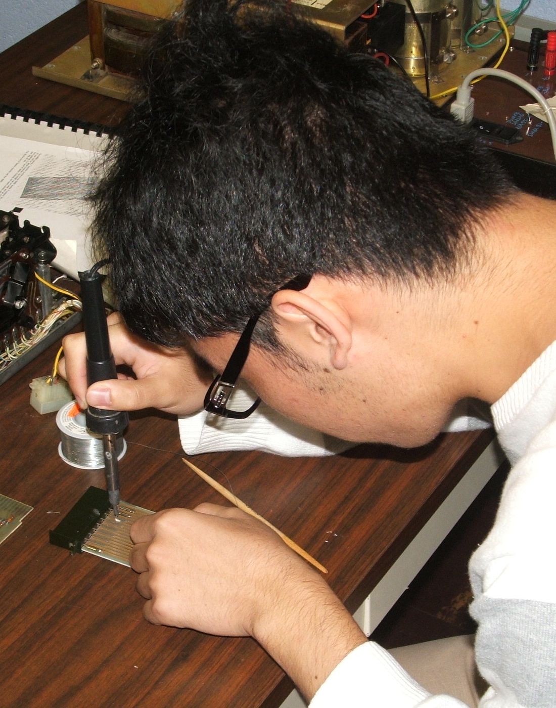
| Soldering lesson and result | |
|---|---|
Assembling the W982 boards required bending a zig-zag into every other lead of the H807 block. This was a bit tricky. We guess that DEC used some kind of bending fixture to do this on a production basis. With the leads bent, soldering the connections to the boards became the topic of soldering lessons for several of the students working on the project. The resulting solder joints were not as pretty as the joints on DEC's boards, but they are sound and the boards should be functional.
Bug 10: After a while at 25V, C1 to C3 in the Type 779 supply were tested. They passed the capacity test (discharging at under one volt per second from 15 volts), but after a fast discharge through a dead short circuit, the voltage rebounded to about 3 volts -- a sign of a high internal resistance betwee different segments of the internal electrodes. These capacitors should not be relied on at the full rated power of the supply, but so long as we never fully configure the rack they powered, they may be adequate.
We started reforming C4 to C6 in the Type 779 supply.
Reverse Engineering
| |
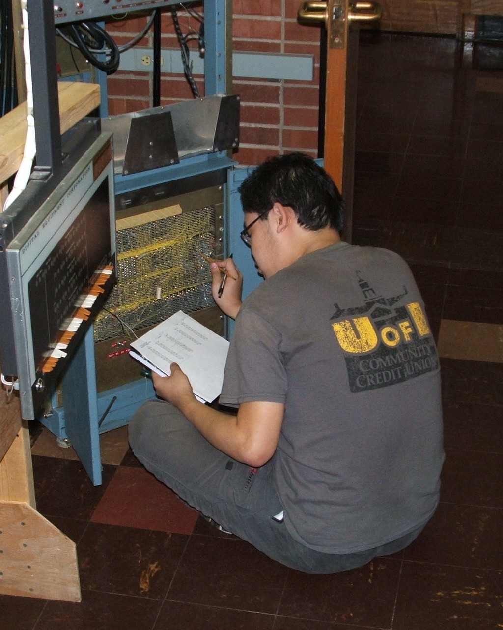
Bug 19: Following up on work done on Mar. 24 and Apr. 29 We have begun using the forms described above to reverse engineer the wiring of backplane slots PA29, PA36 and PB22 in the CPU, in order to resolve whether our CPU is wired differently from the wiring documented in the maintenance manual, or whether it is wired in accordance with the manual. Here, for reference, is the table of discrepanices reproduced from the Apr. 29 log entry:
| Slot | Board Found | Board Expected |
|---|---|---|
| PA29 | R1115 | R603 |
| PB22 | R603 | R111 |
| PA36 | R302 | W501 |
If our investigation of the wiring shows that the backplane is wired for the board found, we must assume that the machine is a variant design that does not match the documentation. If, on the other hand, the wiring matches the documentation, then we will assume that the wrong board was put in, probably after a "tourist" exploring the idle machine pulled some boards and then put them back wrong.
Initial work focusing on PA29 suggests that the board is wrong and the manual is right.
Bug 10: We finished reforming capacitors C4 to C6 in the Type 779 power supply and tested them. As with C1 to C3, the test methodology was the same one used on Feb. 13, 2014: The leakage was checked by measuring the voltage drop across the 510Ω series resistor; in all cases, this was under 0.1mA. After discharging to 15 volts, the rate of discharge through the 510 ohm resistor was measured; in all cases, it was under 1V/s, indicating a capacity on the order of 30,000µF. Finally, the capacitors were shorted briefly while the voltage across the capacitor was monitored. On all of these capacitors, the voltage rebounded a few volts after the short circuit, indicating that approxmately 1/5 of the capacity was isolated from the larger part by a high internal series resistance. This is significantly worse than the capacitors in the main PDP-8 Type 708 power supply, where we did not observe such a large rebound. Nonetheless, with the majority of the capacity available at low resistance, we will not rush to replace these capacitors.
Bug 32:
After testing the capacitors, we began to reassemble the supply.
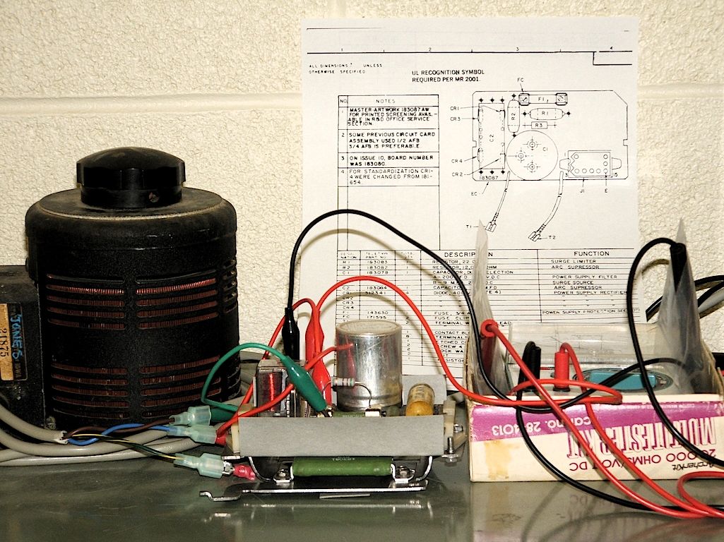
Bug 32: After completing reassembly of the Type 779 power supply, we wired it to a plug and cord and plugged it in. The output voltages, under no load, were:
| Terminal | Measured Voltage |
|---|---|
| Main +10 | +10 |
| Main –15 | –20 |
| Aux +15 | +28 |
| Aux –15 | –28 |
The output of the main +10 supply was exactly as expected, but the other supplies seemed way out of bounds -- that is, until we noticed that the main +10 supply is loaded by an internal 15Ω resistor. This means it is driving 0.66A, which makes the supply output very close to the RMS AC voltage coming out of the transformer. In contrast, the other outputs have no internal load. We had previously noticed that the building power is very noisy. With no load at all, the DC outputs of the other supplies are determined by the amplitude of the high frequency noise spikes on the AC line, not by the RMS voltage.
Just to be on the safe side, we checked the AC RMS voltages coming out of the transformers. The two transformers, marked as being identical, are indeed identical, providing outputs of 10VAC RMS and 15VAC RMS, both voltages measured from the center tap.
Assured that the supply is indeed operating exactly as designed,
we installed it back into place on the rear plenum door of the ADC
rack and re-connected it to the rack's wiring harness.
|
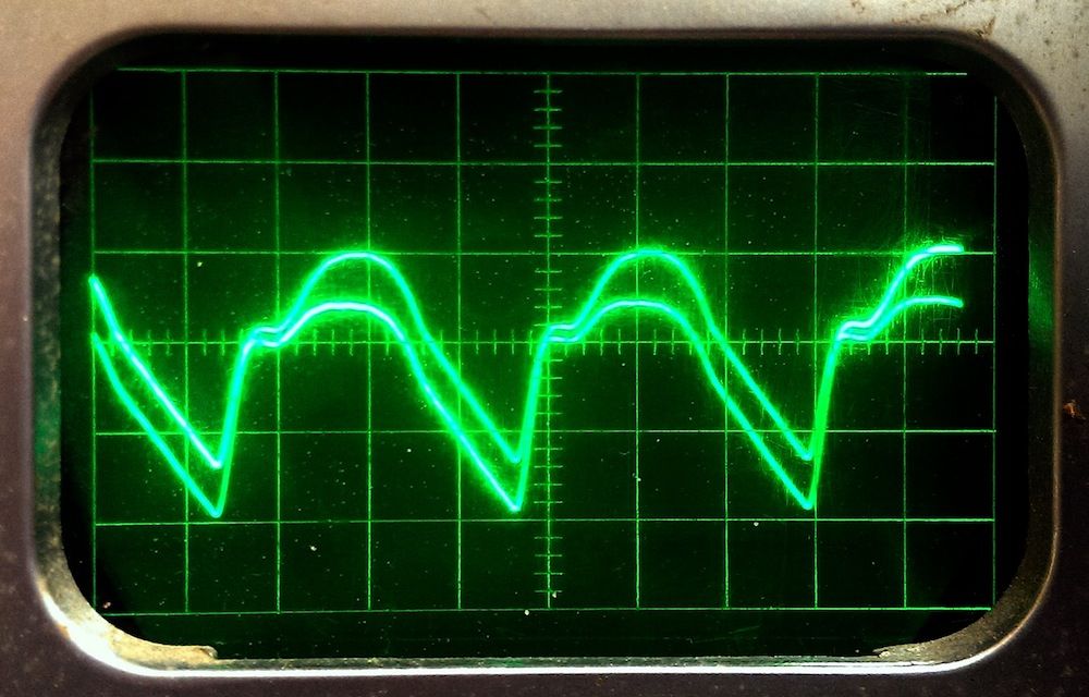
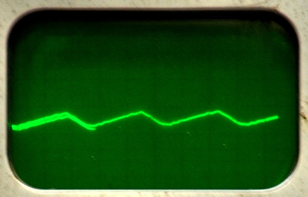
+10V at 6A
| +10V at 10A
|
|
|
–15V at 9A
| –15V at 15A
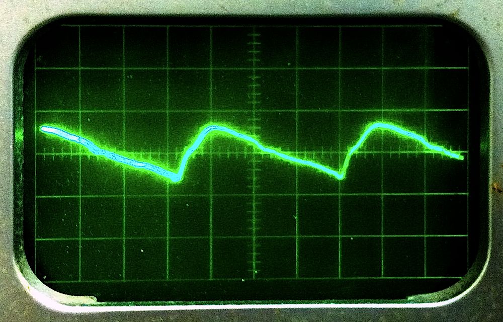
| 0.1V per division
| | |
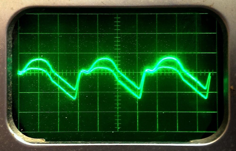
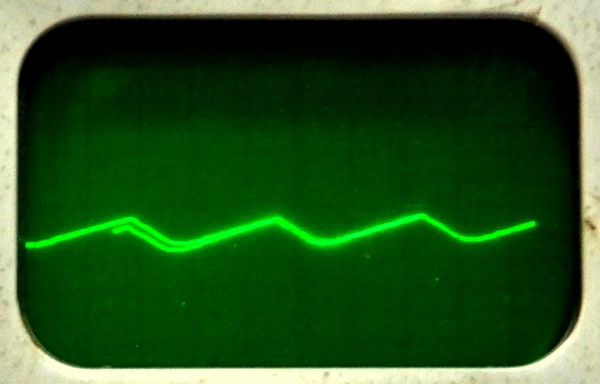
On both the +10 and -15 outputs, the ripple was easily measured on the 0.01V/div scale using a ×10 probe; that is, the horizontal lines in the accompanying screen shots taken by Shanji Wang are 0.1V apart. In all cases, we loaded the power supply outputs that were not under test as in the tests done on Aug. 13: a ~6A load on the +10 supply and a ~9A load on the –15 supply. Note that the power supply specs state that the maximum peak to peak ripple on both these supplies is 700mV, while we saw ripples in the 200-300mV range.
The one concern we have is that the +10 output shows a considerable 60Hz component superimposed on the 120Hz ripple. This shows up as a double-trace on the scope because the scope shows 3 repetitions of the 120Hz ripple. The 60 cycle component does not put the total ripple waveform out-of-spec, but it hints at an asymmetry in the circuitry that ought to be fully symmetrical. David Gesswein found similar problems with the 40V output of his PDP-8 supply. In his case, this was caused by miswiring of the transformer taps — the transformer in the type 708 supply has 3 taps available on each leg of the 40V output, but examination of the power supply schematic shows no such options on the +10V output. Given that the ripple is within spec and the output voltage is right, we will ignore this issue.
By the end of the testing, the total-hours meter had advanced
from 26879.2 to 26879.3 -- another 6 minutes of running time.
|
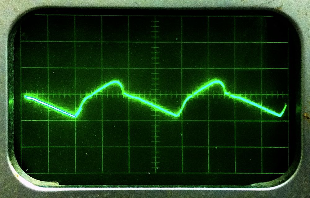
MC +10V at 1A
| +40V at 0.4A
| |
We adjusted the Marginal Check supply for an output of 10V, driving a 10Ω resistor to give a load of 1A. The power supply specs state that the maximum peak to peak ripple on this supply is 700mV, while we saw a ripples of about 14OmV. Again, we used the 0.01V/div scale using a ×10 probe to give a deflection of 0.1V (100mV) per division on the scope screen.
We checked the 40 volt output of the supply, measuring directly across the filter capacitors. This output is not delivered to the outside world until the power OK relay (K1 in the power supply schematic) closes, which it does not. When the power OK relay is open, this supply is loaded with an internal 100Ω resistor (R7 in the power supply schematic), drawing about 0.4A. We observed a clean ripple waveform of about 120mV on this output, the input to the regulated Inhibit and Read/Write supplies.
|
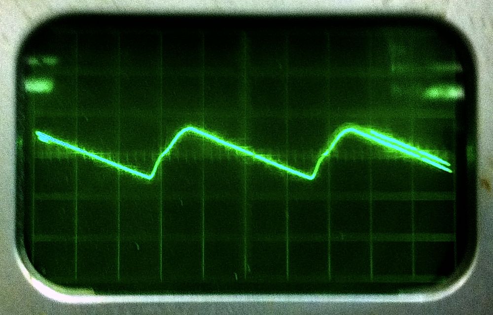
Inhibit -
| Read/Write -
| |
Looking just at the waveforms, both supplies appear to be regulating well,
tracking the ripple on the +40 supply very accurately. However, looking at
the DC voltages, one of the two supplies is not doing its job, with the –
output at +40 volts instead of down near ground. Also, the power-OK signal
is never asserted so the relay connecting the Inhibit and Read/Write outputs
does not close. We need to investigate this further, reopening
Bug 20.
|
Extrusion punch and thread
| | |
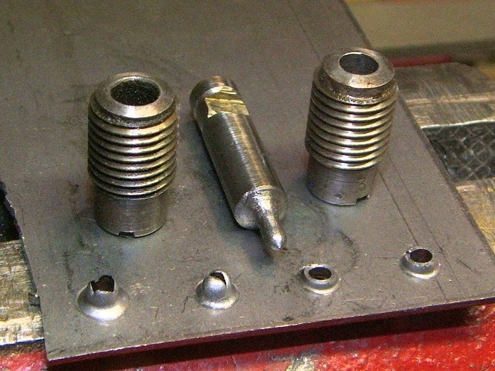
I have seen manufactured parts where the punch used to form the hole extrudes a sleeve on the punched hole in order to support many more threads than could be supported by the thickness of the sheet metal. Web searches using keywords like "extrusion punch", "extrude punch tap" and "extruded hole" located a patent drawing and several tutorials like this one or this one. On the strength of this, we did some experiments.
First, I cut a punch from a piece of 9/32" high speed steel drill rod, the nominal size of the punches used in my Whitney No. 5 Jr. sheet metal punch. This was so close to exact size that it barely fit my punch, so I honed it to a slightly smaller diameter so it would slide freely in the punch. I ground the end to 0.113" (2.87mm) diameter (the size of a tap drill for a 6-40 threaded hole) and then ground a 90° point on the punch, rounding the shoulders so that the punch would compress the rim of the hole outward as it punched. The result has a slight neck in the punch body behind its broadest part. This was an accident, in this case, but it is a good idea as it prevents the punch from sticking in the material. All this work was done using an electric drill clamped in a vise as a lathe and using a hand held dremel tool to do the grinding.
For all punching experiments, I marked the location to be punched with a center punch and then put a drop of oil on the spot. For the first experiment (the leftmost in the photos) I punched into a Whitney 7/32" die (nominal, 5.55mm, on the left in the photo). The die was too large, producing a funnel shaped hole and a very thin walled extrusion. Next (moving to the right in the photos), I used a Whitney 3/16" die (nominal, 4.76mm), producing a nice dome but not cleanly punching through the metal. Annealed mild steel is extremely ductile.
For the final two experiments, I drilled pilot holes before punching into the 3/16" die. Using a 1/16" (1.58mm) pilot hole gave a very clean hole with a flat shiny exit face and a total thickness from the opposite face of the plate of 0.10" (2.54mm). The outside diameter of the extruded boss was 0.158" (4.01mm), implying that the extruded tube has a wall thickness of about 0.022" (0.56mm).
Using a number 58 drill (0.042", 1.06mm), the exit face of the hole was no-longer shiny, but otherwise, the hole was very good, with a total thickness of 0.12" (3.05mm), twice the thickness of the plate, and a boss 0.163" (4.14mm) in diameter, implying that the extruded tube has a wall thickness of about 0.025" (0.64mm).
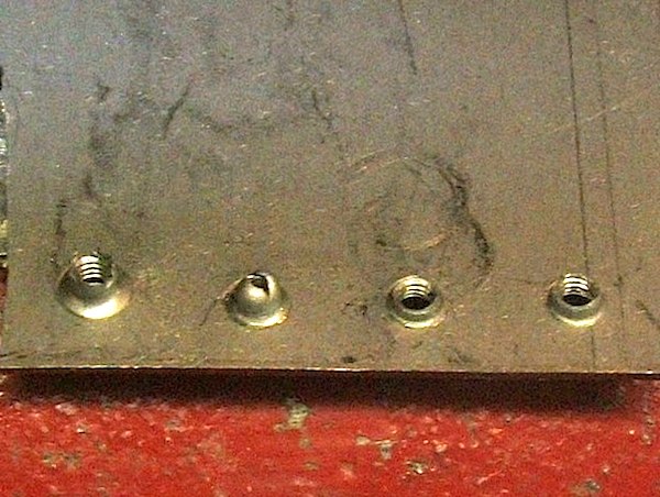
Both of the extrusions punched with pilot holes
were easy to tap. The tapped results are shown in the second photo. You can
easily see in the photos that there are from 4 to 5 full turns of threading
in each of the extrusion-punched holes, twice as many threads as would result
from merely drilling and tapping the sheet metal. Furthermore, punching
should work harden the metal around the threads, making them stronger.
Supply mounting bracket
| | |
I sawed the bracket to size using a handheld saber saw (also called a jigsaw) with a metal-cutting blade. The saw bucked fiercely when cutting 16-gauge steel, hard enough to bend the metal. I solved this problem by clamping the steel to a wood board held in a vise so that the line of the cut was close to exactly on the edge of the board. I had to reclamp the metal for each line I cut along, and I had to push down hard on the saw, but the resulting cuts were good. To guide my cutting, I glued a paper drawing of the bracket to the sheet metal. In making additional brackets, I clamped the first one to the new one and scribed its outline.
I used a hole punch (Whitney No. 5 Jr.) to punch holes tangent to the edge of the bracket at each point where there was an inside corner and at scattered points along outside curves in order to make it easier to turn the saw. This helped quite a bit with the sawing.
|
Reader supply mounted in the CCU
| | |
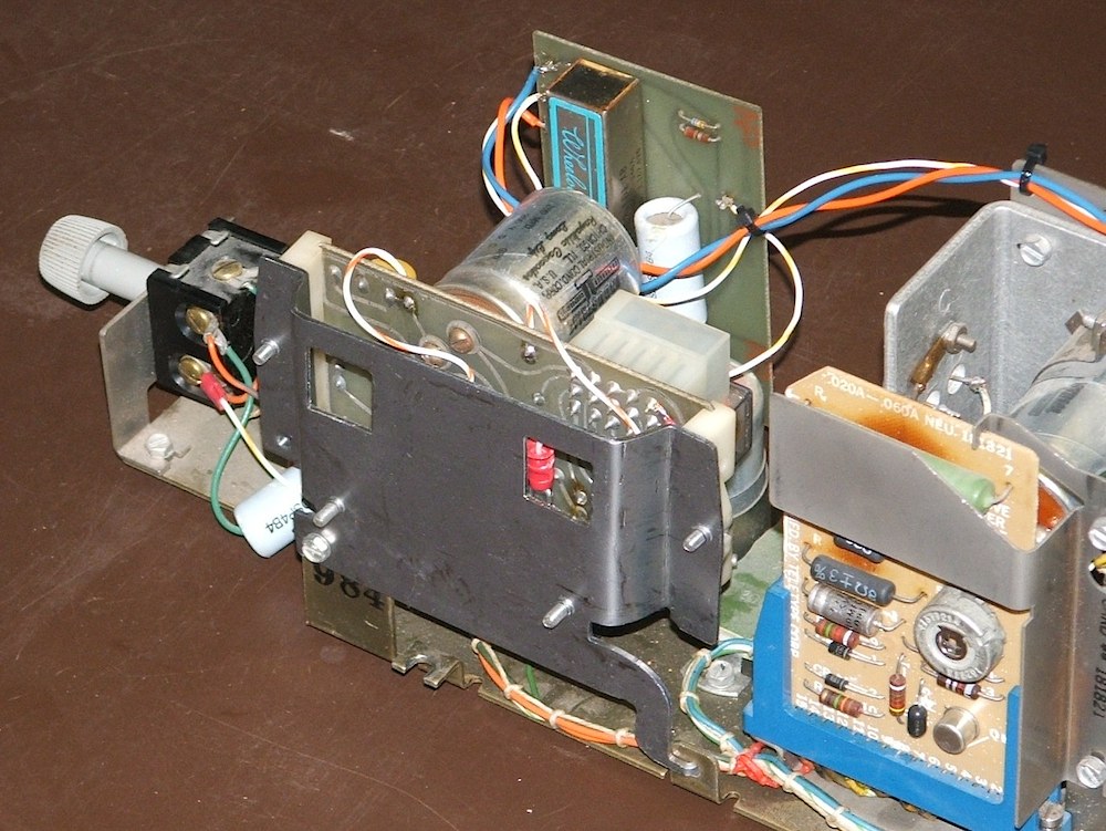
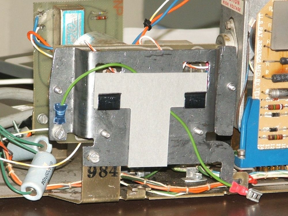
After I screwed the parts for the paper tape reader power supply to the bracket, I mounted it on the Call Control Unit base, as shown in the accompanying photos. Everything fit as intended and the result looks very similar to the photos on the web. The brackets we have found photos of on the web all include one additional detail, a T-shaped piece of red vulcanized fiber attached to the outside of the bracket. Vulcanized fiber is still made. We were unable to find red in the correct thickness (measured from a second piece of red fiber used as a shield on the back of the CCU), but we found grey vulcanized fiber in the correct thickness and we will use that. Some (but not all) of the photos we have found show a fish-paper (grey vulcanized fiber) insulating shield around the power supply (see this photo). We could easily make this, but it does not seem necessary and it is missing in other teletype photos we have found.
Bug 26 and
Bug 39:
While going over the Teletype mechanism investigating the adjustments
that might be needed, we accidentally overtightened a screw that holds the
paper-tape punch to the typing unit, breaking it.
Unfortunately, this was not just any screw, but a very unusual custom-made
screw with a gigantic screw head.
Bug 20 and Bug 36: On Oct. 29, we noted that the Power-OK signal is never asserted and the relay connecting the Inhibit and Read/Write outputs does not close. We speculated that one of the series-regulator transistors might be bad (Q1 and Q2 on the power supply schematic) These are 2N3715 transistors, rated at 10A 60V 150W. They are mounted on the vertical aluminum panel that divides the front and back of the power supply.
Given that one of the supplies appeared to work and the other did not, we swapped the transistors, hoping that this would move the problem. It did not. Therefore, the bug was elsewhere, so we began tracing wires.
Supply mounting bracket
| | |
Some Teletypes have a second piece of fish paper to insulate the supply itself. We have seen teletypes with and without this in photos on the web, so we opted to leave it out on this machine for now.
Bug 10:
We can't power up the Teletype until the capacitor in the tape reader supply is
reformed, so we must return to this problem. This particular power supply
simply rectifies the 110V power from the power line, giving about 150V DC.
Our bench supply does not go anywhere near that voltage, but we began the
process by removing the capacitor from the supply and reforming it with
a series resistor to limit the current (the usual approach), working our
way up toward 50V, the upper limit we can reach with the bench supply.
| left | back | right | |||||
|---|---|---|---|---|---|---|---|
| 1 | 2 | 3 | 4 | ||||
| B | G808 INH | G808 R/W | B | ||||
| A | G809 | A | |||||
| 1 | 2 | 3 | 4 | ||||
| front | |||||||
Apparently, at some point, we must have removed all of the boards from this
little backplane (probably while replacing capacitor C15), and then, while
replacing them, we must have put them back in place in the wrong slots, filling
slots 1, 2 and 3 instead of slots 2, 3 and 4. When we put the boards in
their correct slots and powered up the computer, everything seemed to work.
The power-OK signal was asserted and the relay
(K1 in the
power
supply schematic)
closes sharply on power up, connecting
connecting the Inhibit and Read/Write outputs to the supply.
We saw no evidence of the relay chatter problem documented by David Gesswein
(see his discussion
here,
particularly note the video near the end of the page).
Therefore, we are ready to return to
Bug 33:
testing the quality of the power supply outputs.
Reforming rig
|
|
Fish-paper shield
| |
Bug 38: Note that we have added the formed fish-paper shield to the supply. Forming this piece of fish paper was an interesting exercise. I boiled it for 10 minutes in water to soften it, and then slowly bent the corners over a block of wood to form the correct shape. Finally, I clamped the formed result firmly to hold it in its final shape overnight while it dried. The corners in the resulting piece are well defined, with no cracking. Some of the wood blocks I used in clamping the final shape were varnished -- this was a mistake, because the varnish prevented water from diffusing into those blocks. This led to some warping, visiple in the photo. All of the wood blocks should have been equally permeable softwood, and we probably should have included a layer of paper towel between the clamp blocks and the fish paper.
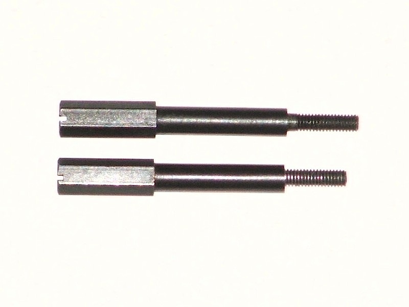
Old and new screws
| |
These are 6-40 UNF screws (these are No. 6 diameter, 40 threads per inch), a screw size Teletype used extensively. While this is a standard size, it is extremely uncommon. Just one machine shop on campus had a few short ones on hand, and Fastenal does not stock this size. Searching the web for sources, it appears that gunsmiths use 6-40 screws to mounting gunsights, and they are used in some guitar tuning heads. The screw we broke has a huge hexagonal head -- it is this huge head that invited the over-tightening that broke the screw.
The head was huge enough that I ground off the stub of the broken screw, drilled and tapped a half-inch hole where the head had been, and (after finding a source of screws on eBay) screwed in an inch-long 6-40 screw into the end. The result is a bit too short -- the inch-long screw went in too far, but we can fix that by dropping a bit of cold solder in the screw hole and screwing the screw into that until it jams.
The trick to drilling a hole into the end of a steel rod is to spin the rod,
not the drill. Ideally, you clamp the rod into the headstock of a lathe and
mount the drill on the tailstock, but the poor-man's approach is to clamp the
rod (or the screw, in this case) into an electric drill and clamp the drill bit
into a vise. If you start the hole well centered with this method, it will
stay centered. I ground off the stub of the old screw with a dremel tool while
the drill was spinning the screw head, and then used a very small grinding tip
to put a dimple in the exact center of the spinning screw head as a
starting point for the new hole.
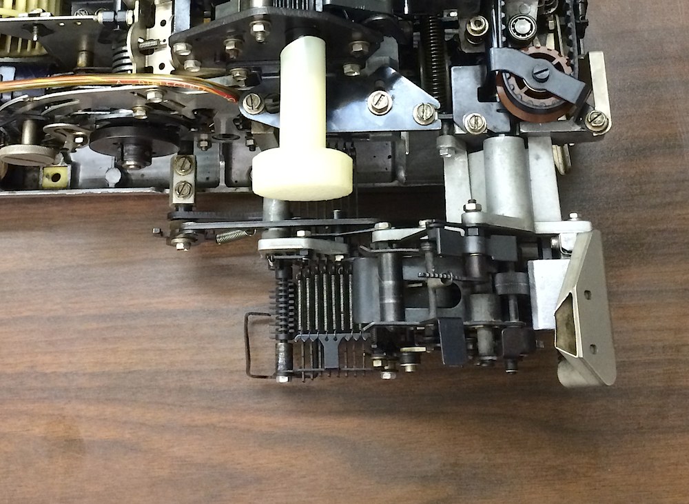
Paper tape punch
| |
We had hoped to re-adjust the length of the repaired screw by unscrewing the stud from the end, adding solder shims, and screwing it back in. This did not work out -- the stud was firmly jammed in and could not be unscrewed without the threat of damage to the screw threads, so we simply used the longer screw where we needed the extra threads, and the shorter one wher the extra threads seemed irrelevant.
Bug 10:
We left the Teletype reader supply idling at 125 volts, having slowly
turned up the voltage over the past few days, gently nudging the variac
knob every five or ten minutes when we were in the lab.
The broken board
| |
The broken socket takes a round pin 1/32" (0.031" or 0.79mm) in diameter (a bit smaller than a 20 AWG wire). Modern headers and wire-wrap pins are usually 0.025, so many sockets that can take such a pin will be very likely to be able to handle the pins on the ends of the sense wires.
Bug 10:
We left the Teletype reader supply idling at 155 volts (full line voltage
as input), having slowly turned up the voltage over the past few days.
While slowly turning up the variac knob, I studied the schematic for this
supply and realized that we have only fully reformed C1A (the larger half of
the 2-part capacitor). The second half has only been reformed to 50 volts
and will require a change in the reforming rig, although it only sees a pulse
of voltage for each character read on the tape reader.
|
|
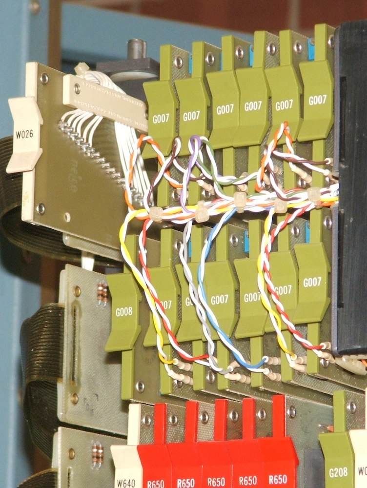
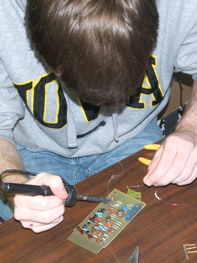
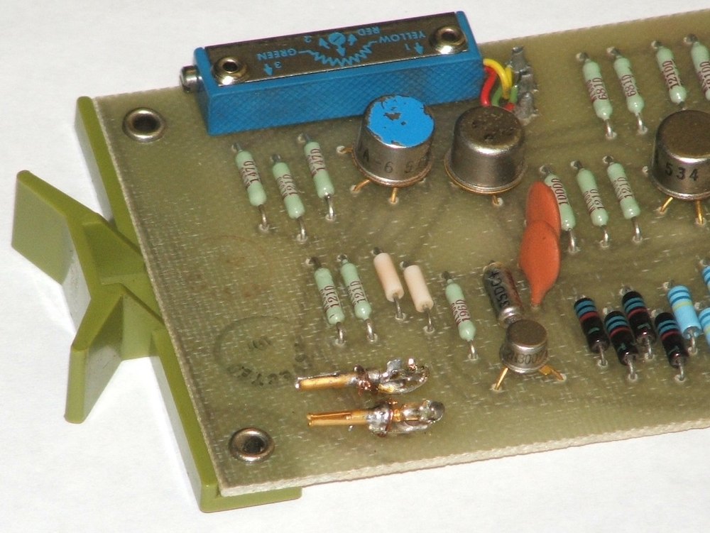
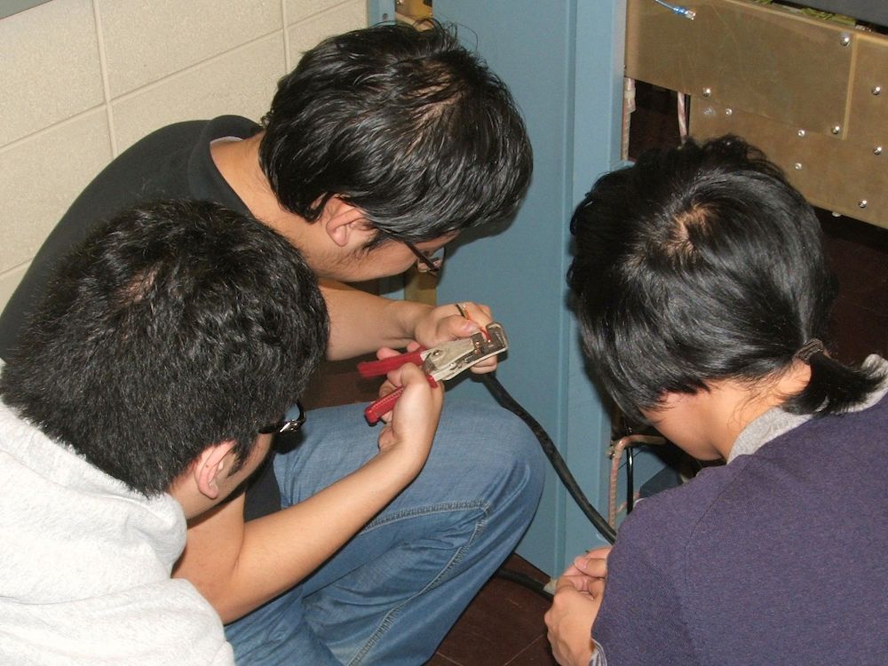
G007 board repair
| | ||
This repair was fiddly three and four-handed work. It was easier to fill the
connector's socket cavity with solder than to get solder to bond the socket
to its foundation, even after we wired the socket in place with a twist of
wire around the barrel of the socket. The left photo above shows Jacob Accord
during an early attempt to solder the connector in place. The other two
photos show the final results. In the rightmost photo, the repaired board is
the lower-left board in the array of 12 G007 boards, with the yellow-white
sense-wire pair plugged into the replaced sockets.
Wire stripping exercise
| |
|
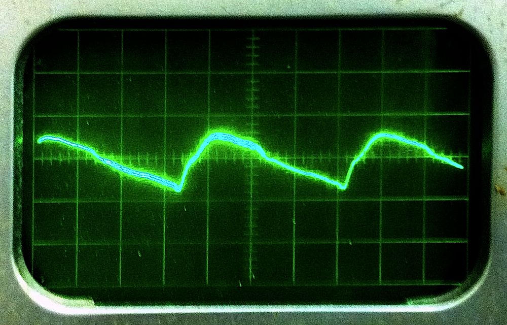
Inhibit
| Read/Write
| |
The key to making these measurements with a single input scope was to float the entire oscilloscope relative to ground. On careful inspection of the manual for the Tektronix 321, I found that, when powered from an external DC supply, it could float as far as 600V from the supply. So, I built a DC input cable for the scope, as documented on the Tekwiki web site, and then powered the scope from the -15V output of the PDP-8 power supply (the scope only needs 0.7A at 11.5V to 22V). The only downside of operating the scope from DC power is that the graticule is not illuminated, so it is difficult to take an exact reading. The graticule divisions are only barely visible in my photos here.
Also note: Running the scope this way, all exposed metal parts of the scope
body are sitting at roughly 40V. I positioned the scope on a pair
of dry wood 2×4s to isolate it from the power supply and relay rack,
and during these tests, I took care not to touch anything but the insulated
knobs of the scope, and then, with one hand behind my back and standing
carefully out of contact with the rack.