
The University of Iowa's DEC PDP-8Restoration Log
Part of
the UI-8 pages
|
The University of Iowa's DEC PDP-8Restoration Log
Part of
the UI-8 pages
|
This is a chronological log of the progress restoring the University of Iowa's PDP-8 computer. Entries are added at the end as work progresses. Click on any thumbnail image to see full-sized image.
|
|
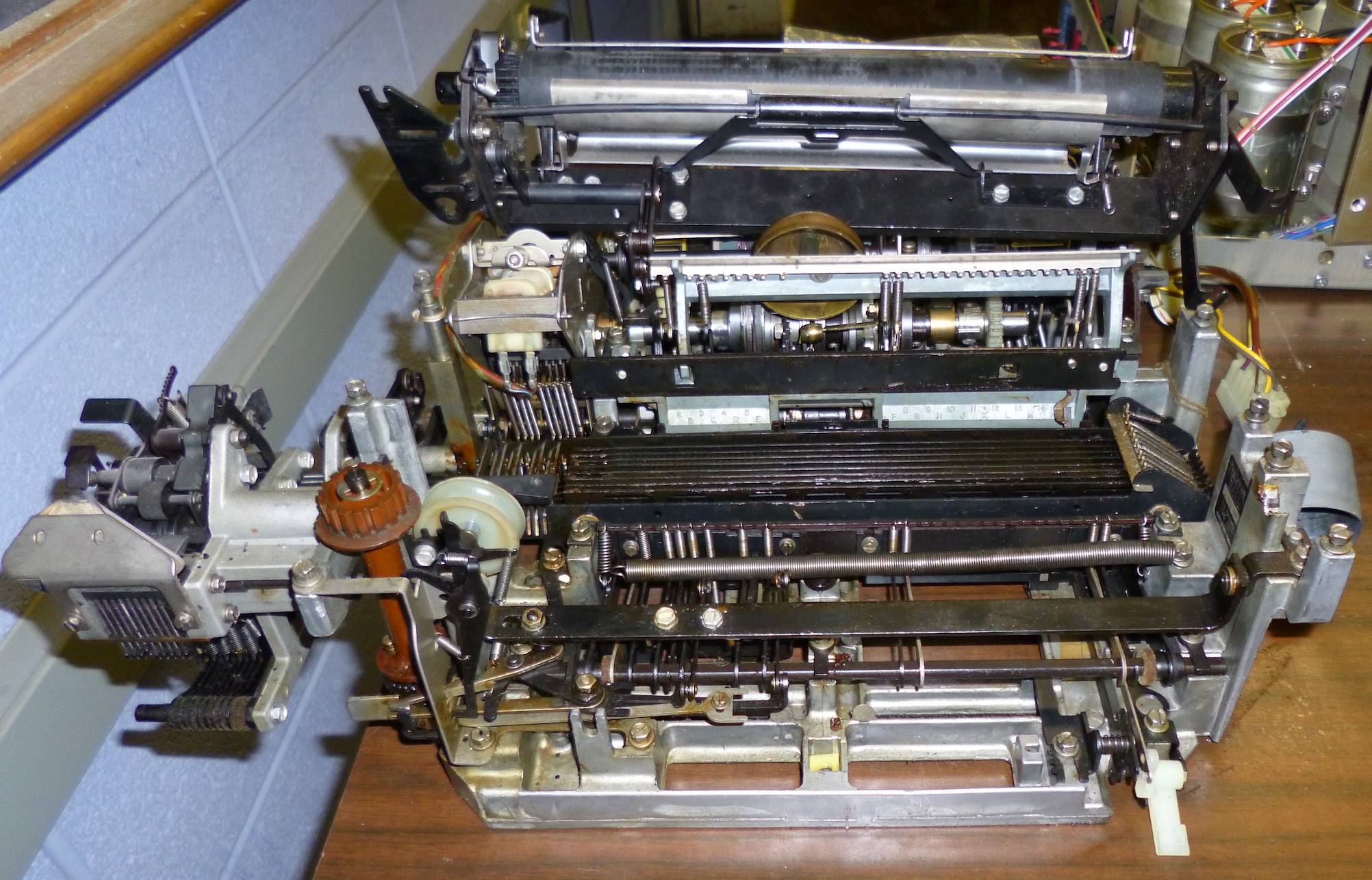
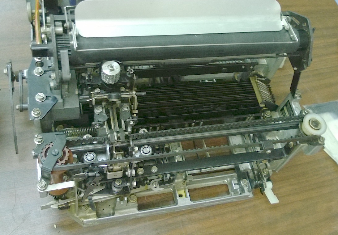
| TTY print mechanism pieces | |
|---|---|
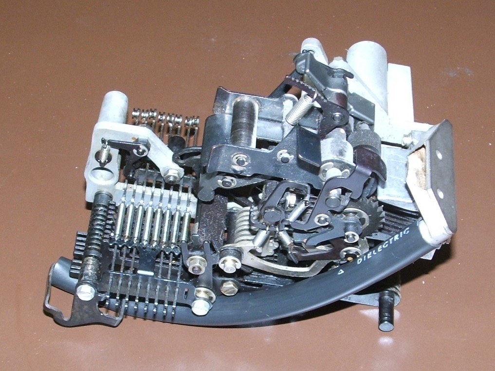
With the print head removed, it is easy to see the cluster of vertical code
bars that extend side-to-side under the carriage. These
rise and fall to convey the ASCII code of the letter to be printed.
The bottom sized of these bars have a system of notches and tabs that make
up the "stunt box" that decodes control characters such as CR, LF, and BEL,
while the heavy horizontal bar across the front of the machine actually
powers the carriage, causing it to raise and rotate the print wheel to
position the right character for printing, and then driving the hammer against
the print wheel.
|
|
| Mounting the new C17 | |
|---|---|
| |
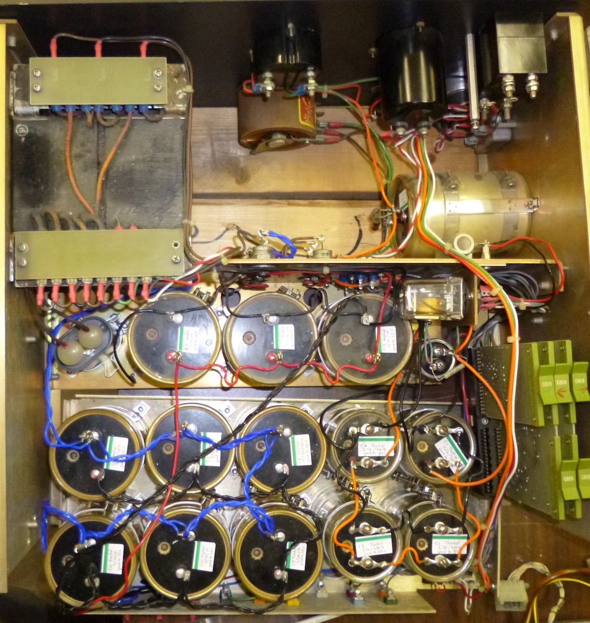
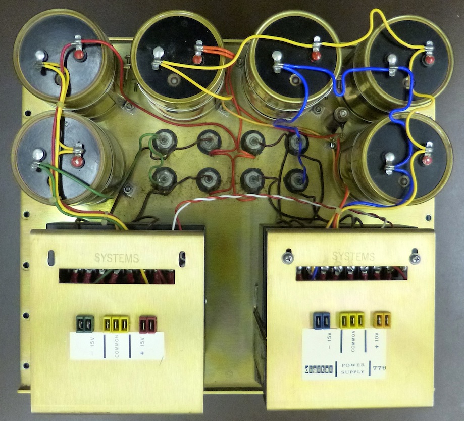
| All of the capacitors | |
With the new C17 in place, all of the capacitors in the supply have been
replaced or reformed. The only job remaining to be completed on the power
supply is that of fixing the broken connectors and, of course, testing the
result.
|
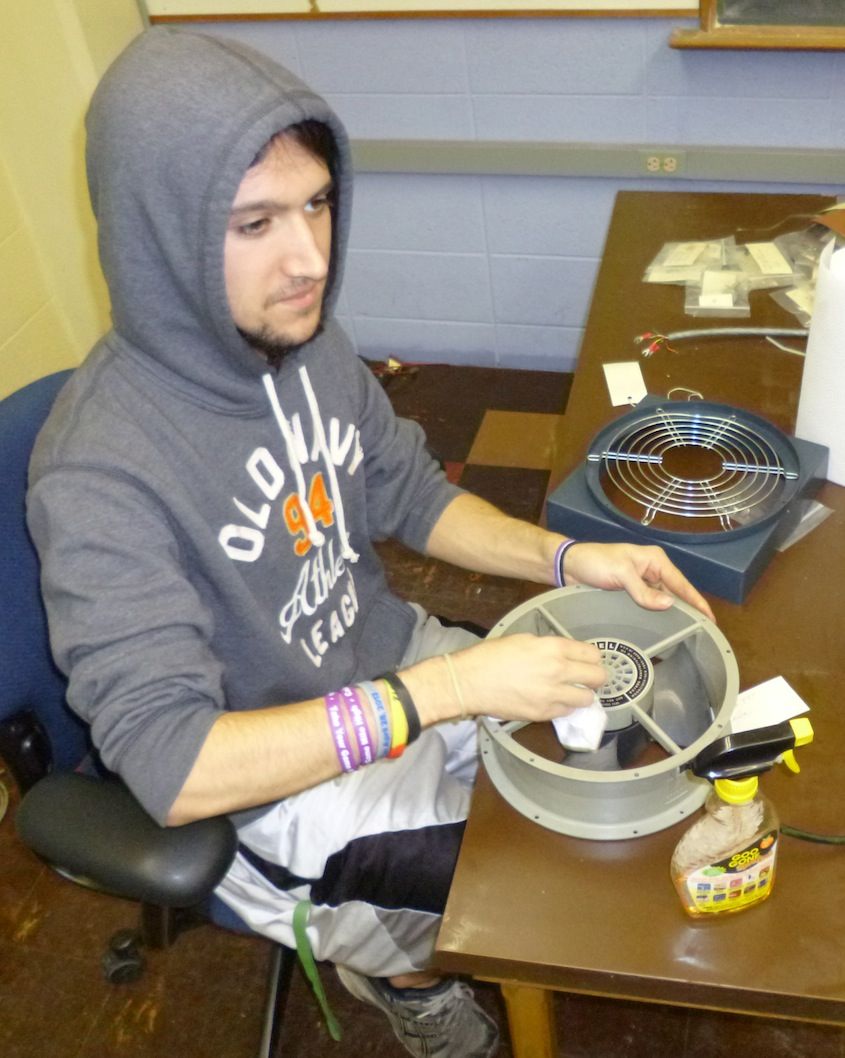
| Fan cleaning |
|---|
The filters are E Z Kleen filters made by Reserch Products Corporation.
This company is still around, doing business as Aprilaire. The filters are
designed to be coated with a product (still available) called
RP Super Filter Coat. U.S. Patent 2,865,466 explains this coating as
a tacky self-emulsifying petroleum product. The idea is that it acts as an
adhesive when the filter is in use, grabbing dust particles, but it emulsifies
in warm water, releasing the accumulated dirt and rinsing off of the filter.
|
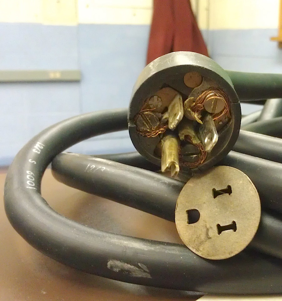
| An unsafe plug |
|---|
|
|
| Tally Reader Disassembly | |
|---|---|
Bug 18: We got a box of 100 screws and lock washers, indistinguishable from DEC's original screws. The correct specification is 10-32 Stainless Steel Truss Head Screws with #10 External Tooth Stainless Steel Lock Washers. All missing screws have now been replaced, and we have many spares.
Bug 25:
We researched the KS7470 that
the Teletype manual calls for, and concluded that it was
equivalent to Starrett 1620 Tool and Instrument Oil, which we then
ordered.
|
|
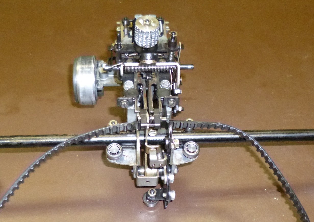
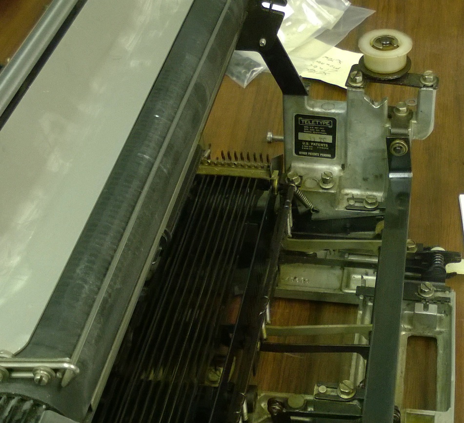
| The Teletype punch and print unit base | |
|---|---|
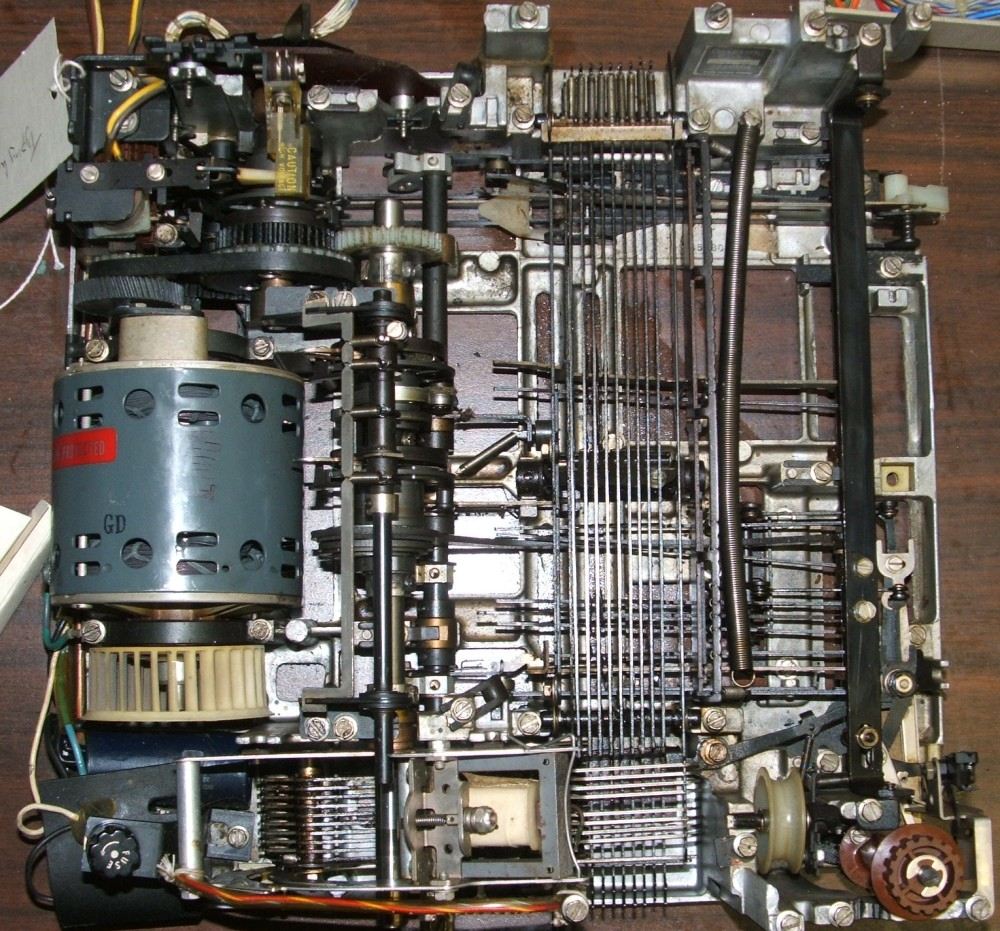
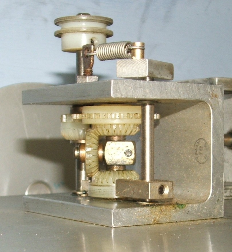
In the photo of the Teletype print unit base, the code bars run vertically.
These carry the ASCII code of the character to be printed, being "read" by the
carriage from above. The horizontal bars below the center portion of the
code bars are the "stunt box" that decodes the control characters to actuate
carriage return, line feed, bell and other non-printing functions. The shaft
extending vertically between the motor and the code bars is the main cam shaft,
while the selector magnet is at the bottom center. The latter actuates the
code bars, with a cluster of cams on the camshaft used to determine which
code bar is being addressed at each instant.
|
|
| Tally 424 capstan and take-up reel drive | |
|---|---|
| |
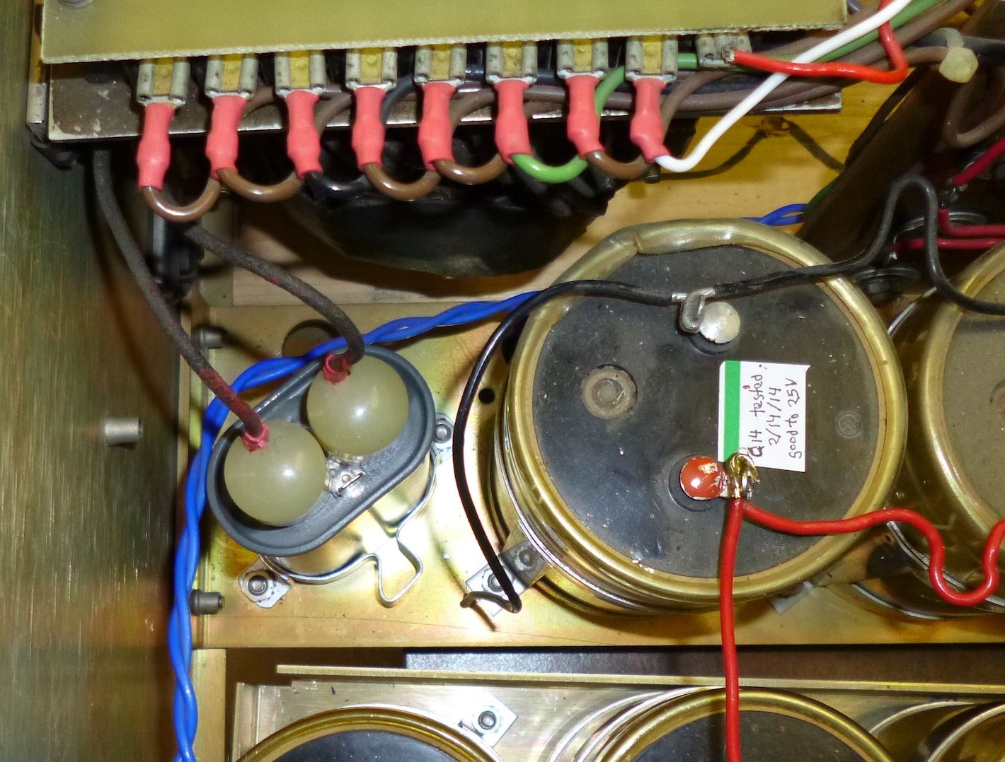
| Motor Run Capacitor | |
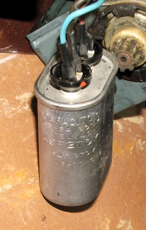
Bug 29: In disassembling the reader, we realized that, as with the PDP-8 power supply, this reader includes a motor-run capacitor that is probably PCB-filled and devoid of internal protection. As these are prone to explosion and constitute an environmental hazard, we will replace it. The engraved markings on the capacitor read:
| CAPACITOR | GE |
| 62-34 60CY | |
| MADE IN USA | |
| 49F2707 | |
| 3Uf370V | |
| 46-00-014 |
That is, this capacitor was made by General Electric in the 34th week of
1962, and it has a capacity of 3 microfarads at 370 volts.
|
| An RS-232 converter |
|---|
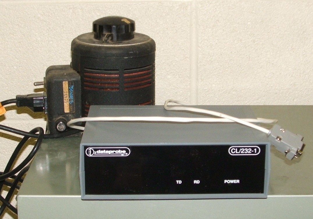
The CL/232 converter was made in the 1980s and never used until this year,
so its power supply capacitors were in as much need of reforming as those in
the PDP-8. Its power supplies are all simple
linerar supplies, so we hooked it to a Variac and slowly raised the
line voltage over a period of a week in order to reform the power supply
capacitors. We also built a cable for it to connect to the serial port
of a Raspberry PI computer. We still need to construct the cables needed
to connect it to the PDP-8.
|
| Reader-run relay |
|---|
|
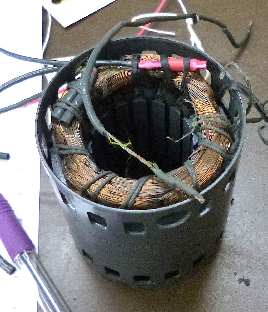
| Motor rebuild |
|---|
The most time-consuming part of the motor rebuild process was removing the
old lacings on the end of the motor winding and re-lacing the windings.
This was necessary because the crimp connectors connecting the motor leads
to the windings were held in by the lacings, and any strain on the leads was
taken by the lacing. We used new waxed lacing tape and did our best to
duplicate the origina lacing pattern. Note that the crimp connectors we
replaced were more compact than the new ones, but tight lacing holds the new
bigger connectors down so they just fit inside the motor end caps.
|
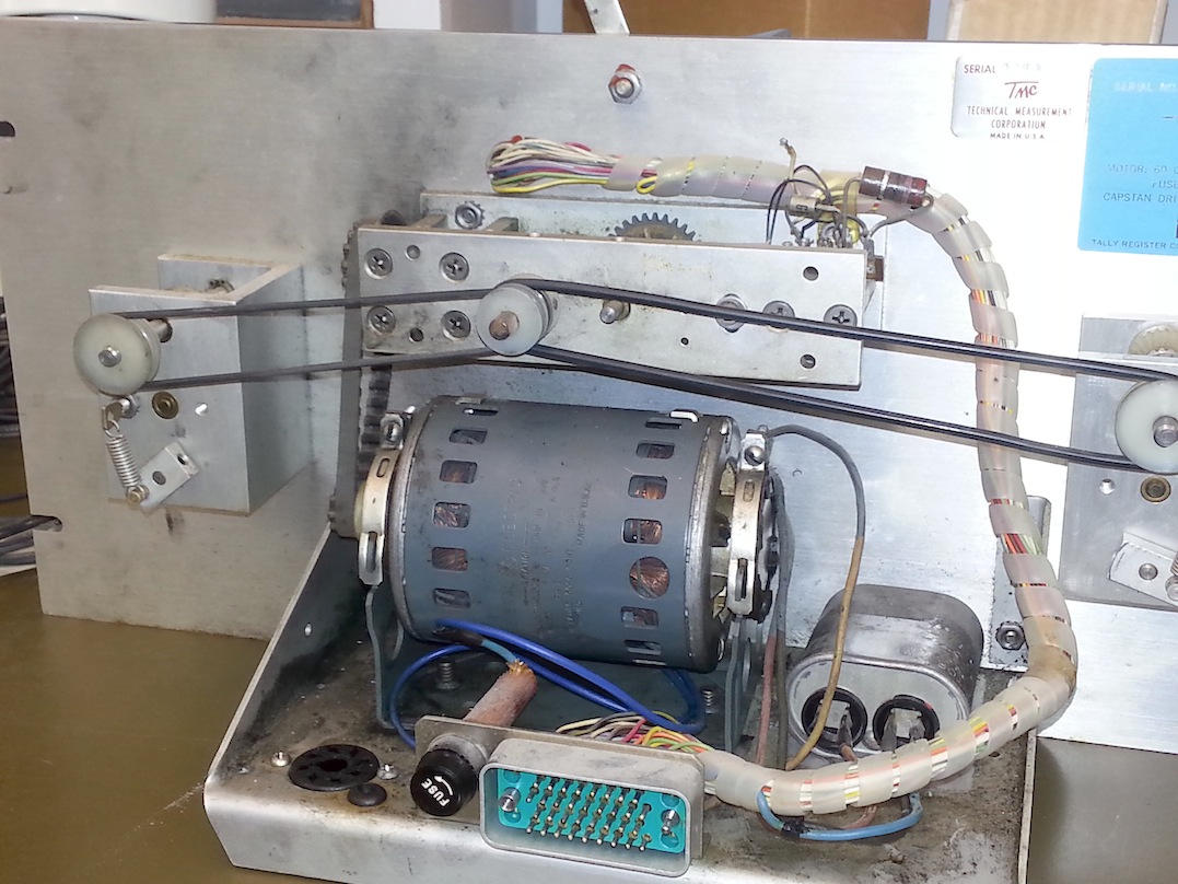
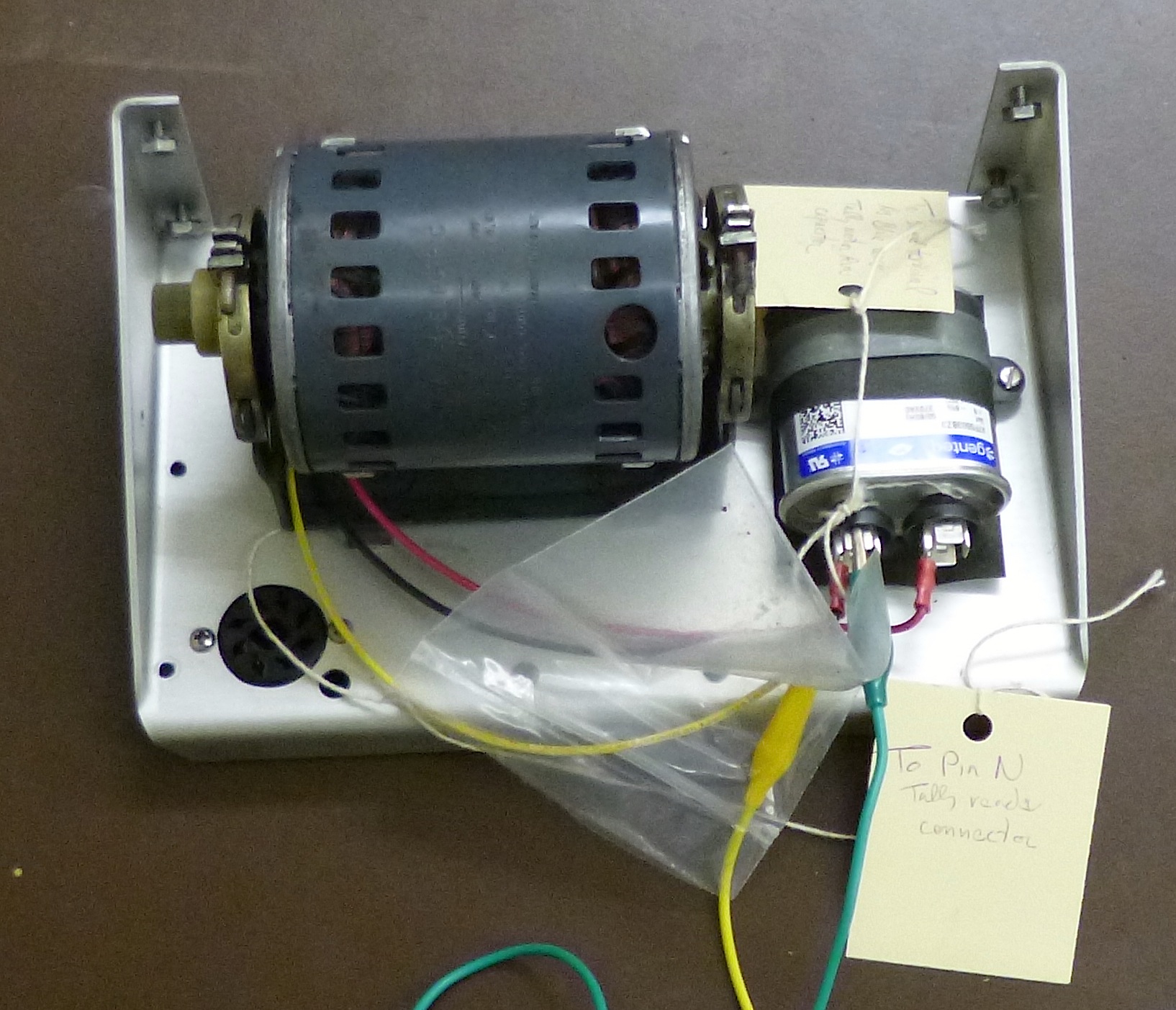
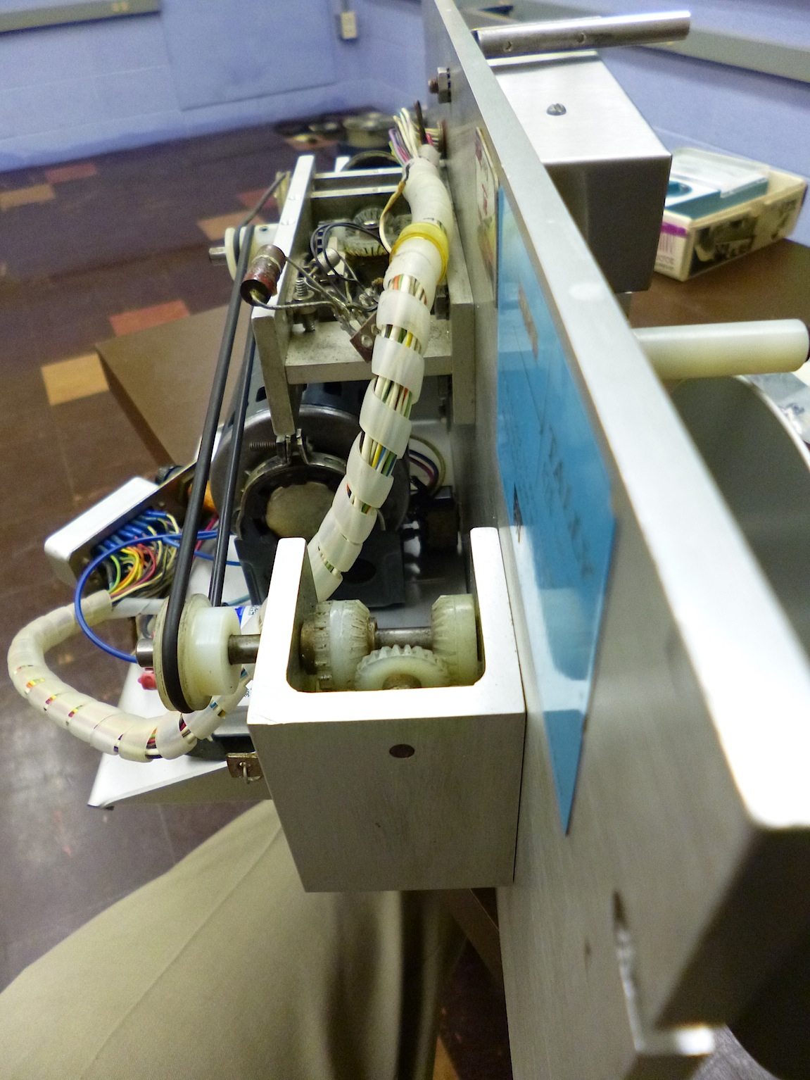
| Motor testing |
|---|
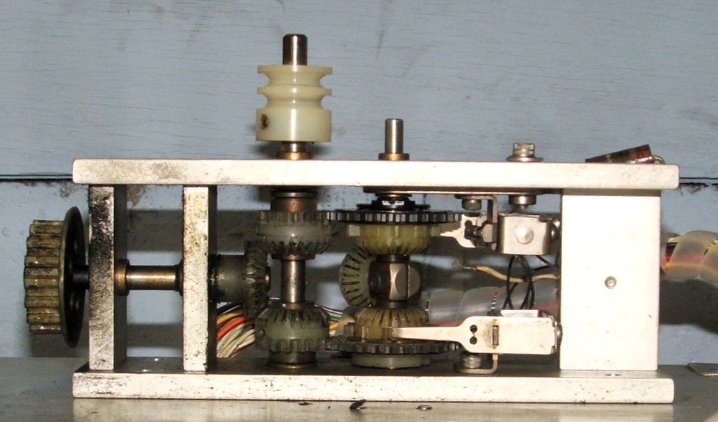
Before reassembly, all wires were tested statically for
continuity through the motor with an ohm-meter, and after reassembly, it
was verified that there was no conductive path from the motor windings to
ground. Then, as shown in the photo, the motor was powered up with
clip leads, using baggies over all clip-lead to wire connections for
safety. The drive gear on the left end of the motor is a blur in the
photo because it is spinning. The motor ran almost silently, and after
running a few minutes, it was warm but not hot. With an AC voltmeter,
the motor housing measured about 20 volts, but this was at a very
high source impedance, almost certainly the result of capacitive coupling
to the motor windings, as DC testing of the motor after installation
confirmed again that there is no DC path from motor windings to housing.
Bug 26: Cale Bierman and Matt Adamczyk began reassembling the Teletype after degumming was complete.
Bug 19: Tony Andrys has completed the backplane inventory for the PDP-8. We have confirmed 3 serious discrepancies where it appears that the wrong boards are in the wrong slots, probably the result of "tourists" pulling random boards to show them to people and then putting them back in the wrong places. Specifically:
| Slot | Board Found | Board Expected |
|---|---|---|
| PA29 | R1115 | R603 |
| PB22 | R603 | R111 |
| PA36 | R302 | W501 |
We will need to do some reverse engineering of the wiring for these slots in order to verify whether they are wired for these anomalous boards or wired in conformance with the documentation.
|
| Installing a rivnut |
|---|
Rivnut installation tools are widely available for $20 or more, but an
improvised tool can be made from a stack of washers, a hex-head or allen-head
screw, a nut and a pair of wrenches. We made such an improvised tool and
used it to replace the missing rivnuts.
|
| TTY reassembly |
|---|
|
|
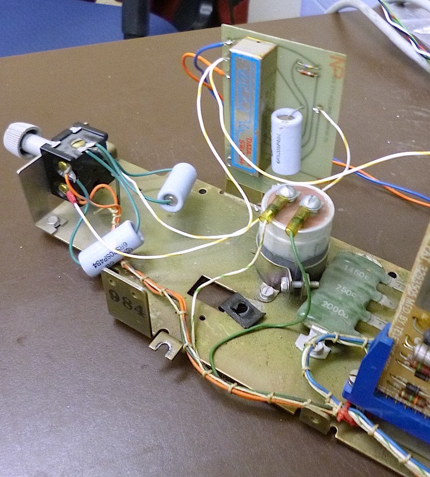
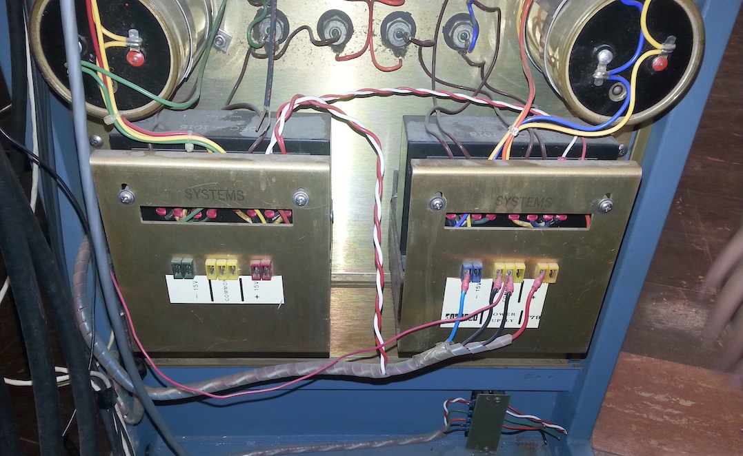
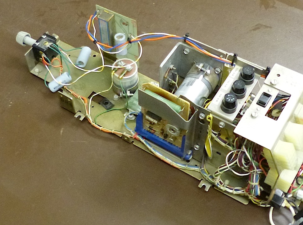
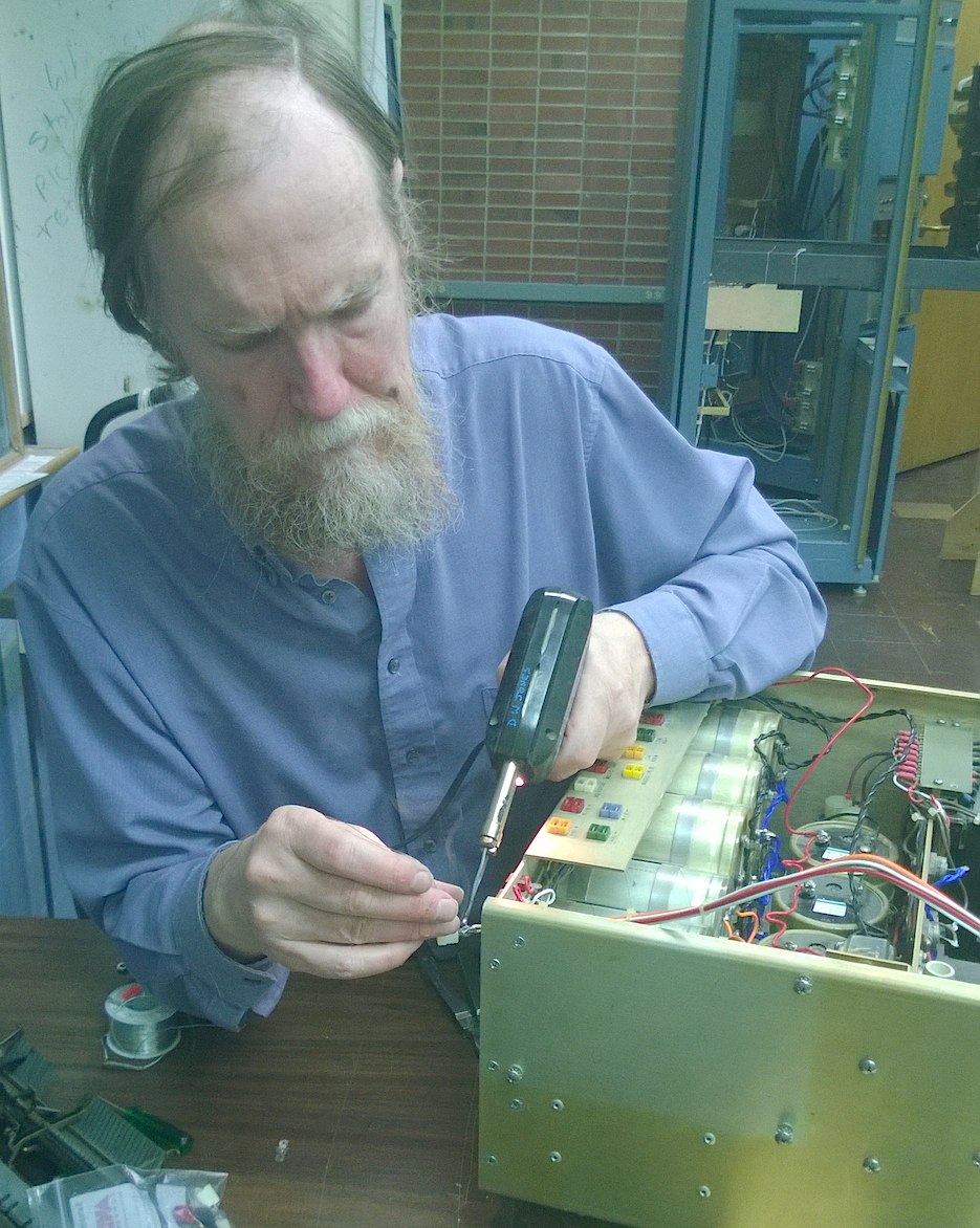
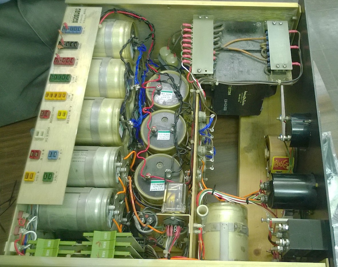
| Type 709 supply and odd wiring | |
|---|---|
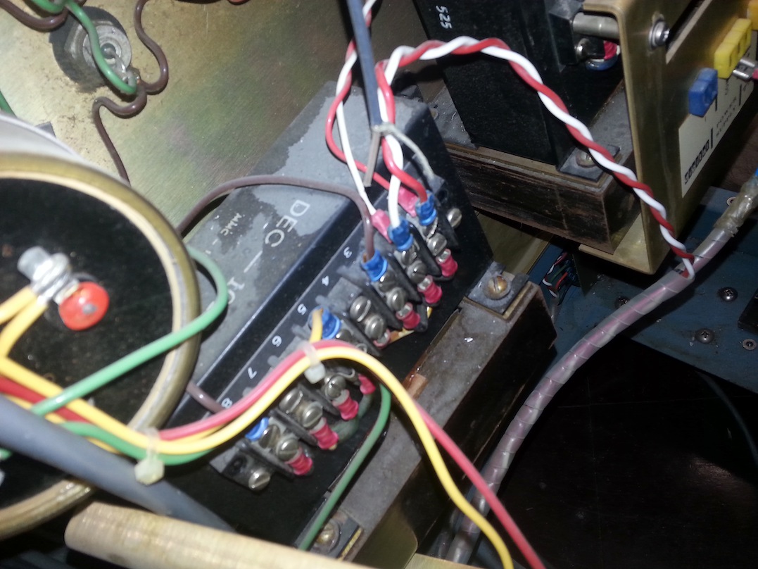
|
|
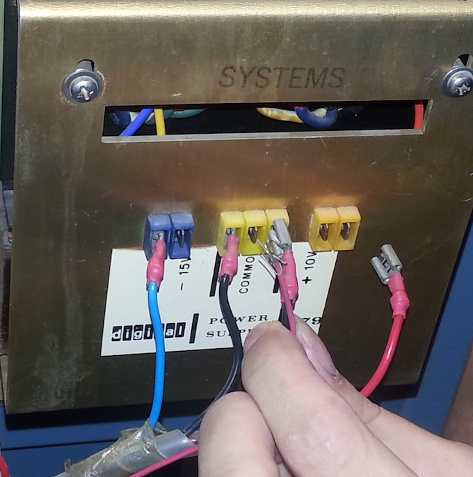
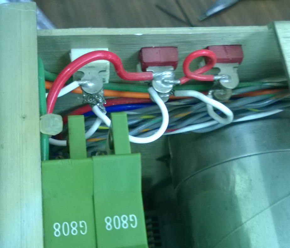
| Supply wiring details | |
|
|
| |
| Completed CCU changes | |
|---|---|
See the log entry for March 20
for the terminal strip connections in the Teletype and the pinout on the
6-pin Jones plugs in the cable.
|
| The doorstop |
|---|
The magnetic latches extend to almost an inch above the bottom threshold and
are almost six inches apart.
When the doors are held so that their front surfaces are coplanar, the
latches are about half an inch forward of the line through the two doorstop
mounting holes. From this, we inferred that the doorstop had been a piece
of 1" angle iron 6" long. We fabricated a new stop and installed it, as
shown in the photo. The iron is unfinished, with
the front surface polished to a high shine using a wire brush. It might be
appropriate to paint it, but the few poor images we have found of
similar DEC racks show a shiny metal doorstop.
|
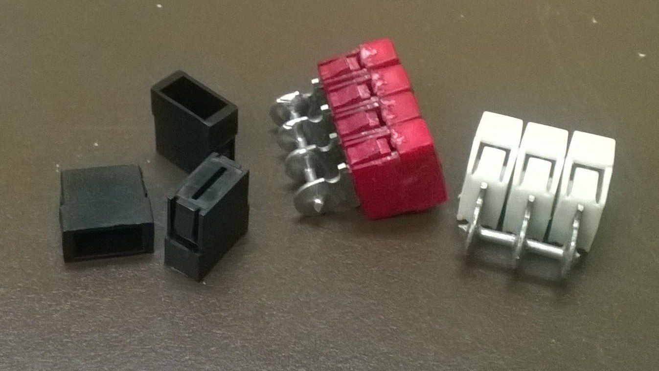
| Replacements |
|---|
|
|
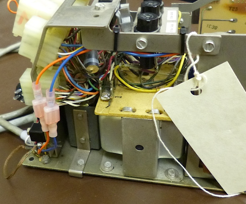
| Repairing the Type 708 supply | |
|---|---|
| |
| Replaced zip ties | |
|---|---|
|
| Putting it back in the rack |
|---|
Bug 33. The next stage in this project will be to test the reassembled power supply. This must be done before attaching the supply to the PDP-8. Ideally, we will need to attach dummy loads for each of the supply outputs, and then turn on the supplies and measure both the DC output voltage and AC ripple voltage on each output. Only after we confirm that all of these are correct should we risk connecting the power supply outputs to the computer.
|
|
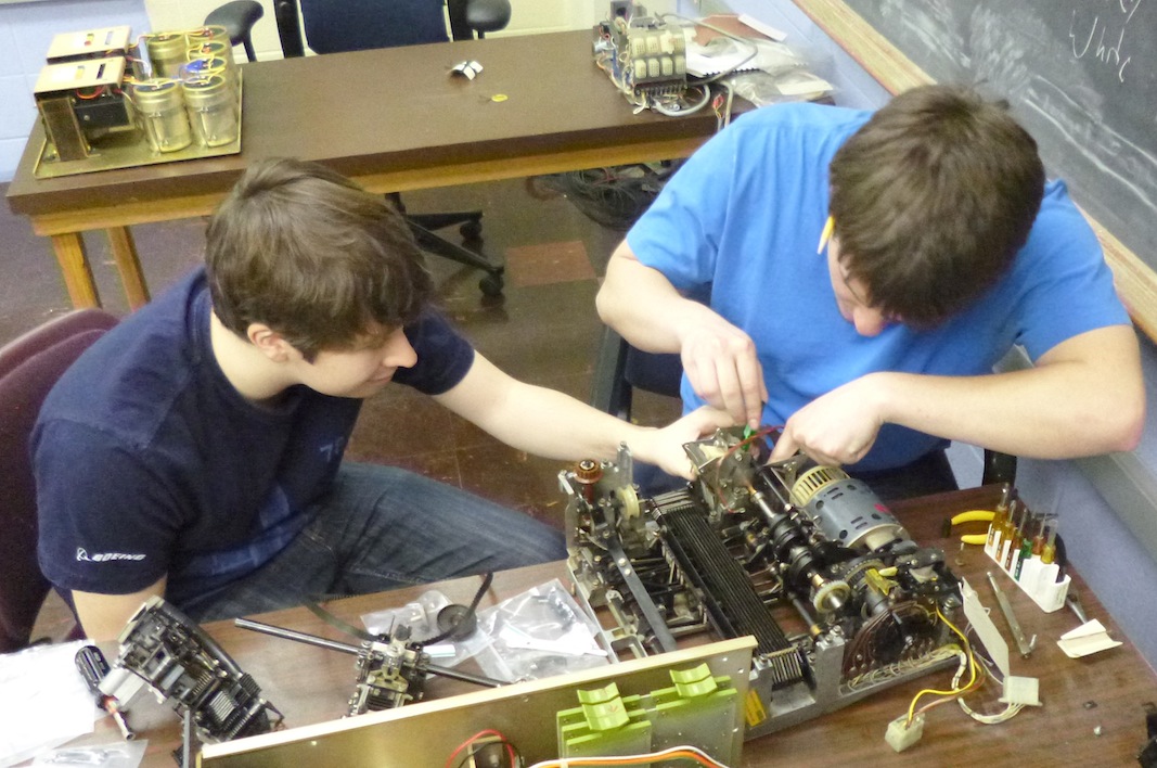
| Typing unit reassembly | |
|---|---|
| ||||||||||||||||||||||||||||||
Assembly took hours. This was despite careful disassembly, with photos, notes, and the various diagrams in the manual, and despite tagging each piece during disassembly. All the small bits were in baggies with labels, and large bits were tagged with string and a label. Despite all these precautions, we kept encountering little bits of Teletype and saying "what's this?" Some parts (such as the right carriage motion pulley mount) could be put on two different ways, and were initially put on the wrong way around. You can see this mistake in Matt Adamczyk's photo of the Teletype label.
Several times, we thought we had the job done, only to pick up the Teletype
and find a spring on the table under it, or a screw. Eventually, we ran out
of parts and, turning the motor or moving the carriage by hand, everything
seemed able to work. We will need to carefully go over all of the adjustments
in the manual, and oil or grease all the lubrication points noted in the
instructions before we power anything up.
|
| The spare |
|---|
|
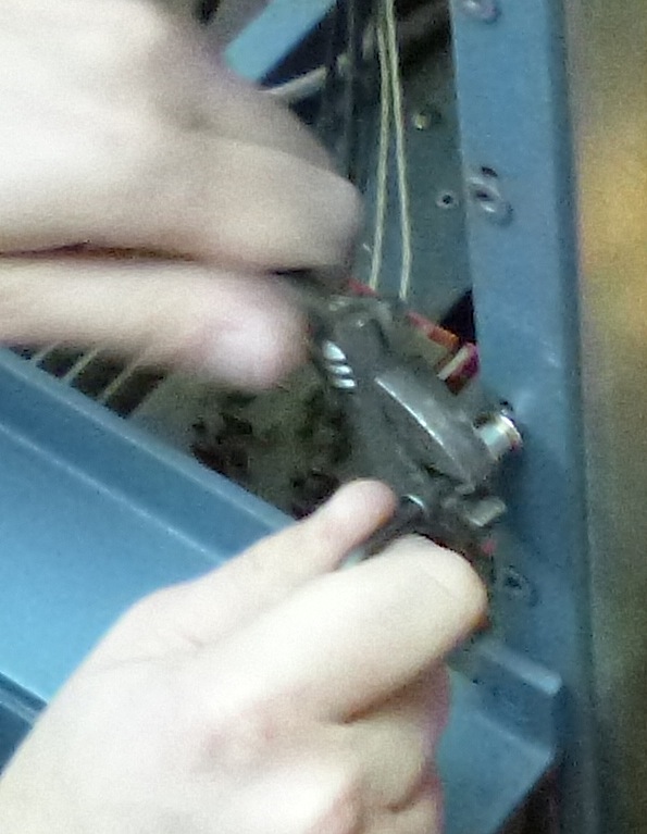
| Reassembly |
|---|
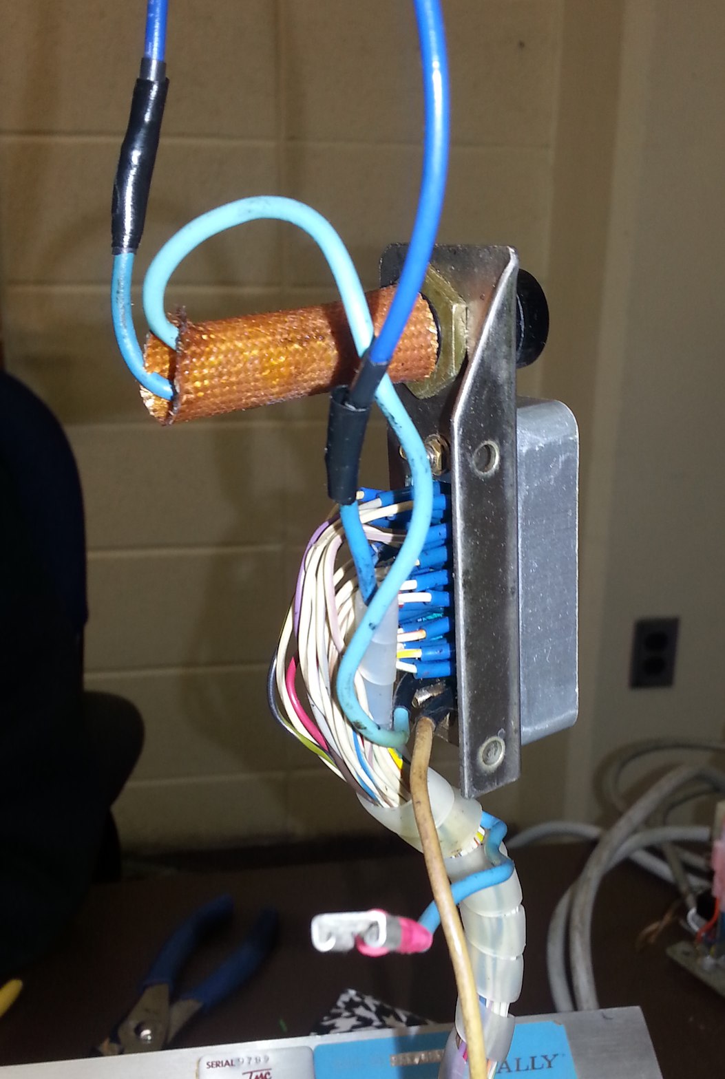
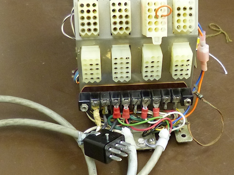
The switch allows users to turn off the motor when the reader is not in use.
The switch the Psychology department used has terminals that protrude to
the rear, and when we put the switch in place, the motor mount shorted to
one of the terminal tabs. The back side of the switch is visible in the
exact center of the photo, with the shiny connector lugs protruding back
under the motor. A short circuit here could connect 110
volt power wires to the frame of the reader.
I reduced the danger by carefully bending the tabs so
they would not contact the motor mount, but we should go further and
slip insulating sleeves over these tabs.
|
|
| Computer Cable |
|---|
There are 6 cable sets connecting the two backplanes of the PDP-8. Each set is terminated, at both ends, with a W034D Flip Chip connector paddle. Stretched out on a work table, the cable sets measure 23 inches from card-edge connector to card-edge connector. There are two flex-print ribbon cables in each assembly, one about 21 inches long, one about 19 inches long. The final 1/8 inch of each cable has had the mylar stripped away so that the foils protrude for soldering.
Each flex-print ribbon has 19 conductors, spaced at 18
conductors per inch, making each cable about 1 3/36 of an inch wide.
These are apparently copper plated onto one sheet of mylar, and then etched
to make printed-circuit conductors before being coated with an insulating
layer to make the finished cable. I speculate that the goo is the result
of the depolymerization of the insulating layer.
Bug 28: We finished reassembling the Tally reader and checked the electrical continuity of all of the wiring, making reference to the schematics in Figure 9 on page 8 of the Tally manual. Aside from the omission of the end-of-tape switches and capstan commutator options, we noted the following discrepancies. For each, we provide a new drawing; in all drawings, the connector is shown as seen looking at the pins of the rear-facing plug on the back of the Tally reader. This is a Continental Connector Corporation Series 20 34-pin connector.
|
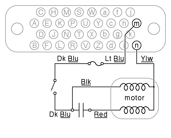
| Motor Wiring |
|---|
Second, the a power switch was added by cutting the light blue wire between the
capacitor and the fuse and then splicing in longer dark blue wire to connect
to the switch. In the process of reassembling the tape reader, the cut
fragment of light blue wire on the back of the fuse was removed and
the dark blue wire was reconnected to the switch.
|
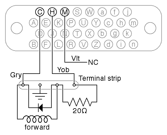
| Tape Advance Wiring |
|---|
The Tally manual discusses the use of a snubber or spark suppression circuit on page 6 and page 9, but it does not say where to mount it physically. On our reader, the snubber was mounted on the terminal strip. In fact, given the length of the cable between the escapement coil and the driving circuitry, the snubber inside the Tally reader will not generally suffice. Additonal snubbing must be provided at the point where the drive pulses are actually switched. The Tally manual documents the use of a resistor-capacitor snubber but what we found is either a diode snubber or a more sophisticated varistor-based snubber (we did not look up the device).
|
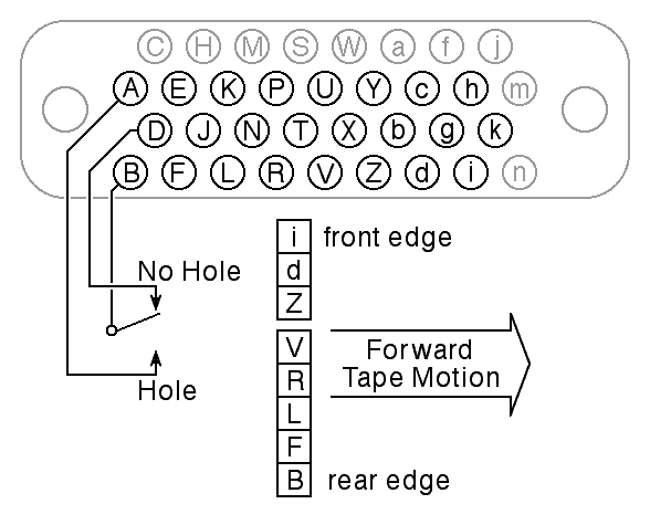
| Data Wiring |
|---|
The Tally reader needs lubrication. The lubricaiton instructions are in Figure 12 on page 11 of the Tally Manual, with accompanying text in Section 5.1 on page 10. The 350 centipoise Silicone oil required appears to be equivalent to. Dow Corning DC200, 350CS; A quick check shows that this oil is available on eBay in 4oz bottles. The SAE-20-grade oil requirement should be satisfied by the KS7470 oil recommended for the Teletype. The Tally pivot grease A required for the escapement armature lever fulcrums is more problematic. Perhaps KS7471 grease (or equivalent) will suffice.
Bug 34:
The Tally reader interface on the PDP-8 ADC rack needs to be reverse engineered.
What we have determined from the reader itself is that this reader has a very
simple interface, but unfortunately, that means that the interface logic
on the PDP-8 end must be somewhat different from that anticipated by DEC.
|
| Cable Wiring |
|---|
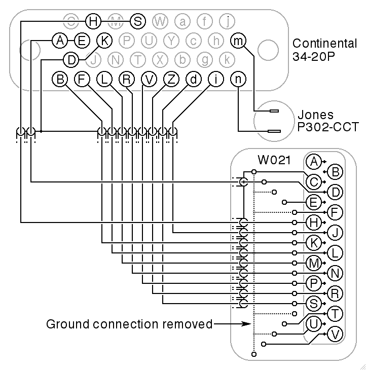
The engineering of the cable is suspect. The data rate on this cable is 60 pulses per second. At this data rate, there is absolutely no reason to use coaxial cable for each data line. DEC routinely used ribbon cable for such interfaces, and we have a new, unused ribbon cable attached to a W021B connector, still in its factory original packaging from 1968. It has only 2 feet of ribbon cable, but we can get new ribbon cable that exactly matches the original.
A second troublesome feature of the Tally cable involves changes made to
the W021 connector at the computer end. As made by DEC, each coaxial cable
is supposed to be connected to consecutive tie-points on the connector paddle,
with just 9 data conductors and 9 (or 10) grounded shield connections
tied together by ground traces on the paddle.
As we got it, the ground traces connecting these tie points have been
removed (peeled off of the printed circuit board), and instead,
the shields of the coaxial cables have been soldered together in a glob
at each end.
|
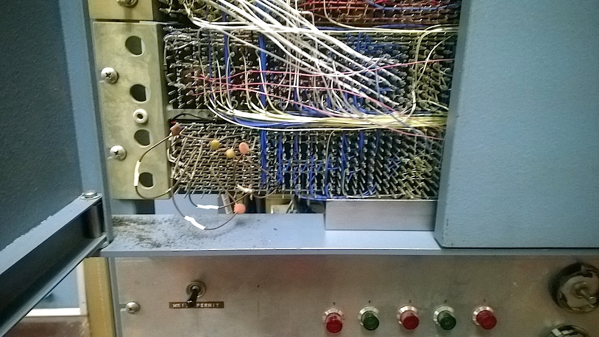
| Backplane Wiring |
|---|
Therefore, without doubt, we must build a new cable. The most conservative
option, from the point of view of future maintainability of the system,
would be to undo what were apparently local modifications to the paper-tape
reader and return it to its factory original wiring, and also redo the
wiring of the backplane so that the connector can be used in more or
less the way it was intended. It should be possible to interface to the
Tally reader using just 9 wires, although half-amp tape advance pulses
should be isolated from the backplane as much as possible.