
The University of Iowa's DEC PDP-8Restoration Log
Part of
the UI-8 pages
|
The University of Iowa's DEC PDP-8Restoration Log
Part of
the UI-8 pages
|
This is a chronological log of the progress restoring the University of Iowa's PDP-8 computer. Entries are added at the end as work progresses. Click on any thumbnail image to see full-sized image.
Bug 67: Continuing the work from Dec 16, 2024, we found a second G209 board that was equally bad. As with the first bad board, all of the bad diodes were on the bottom (B-side) of the board. Some diodes were shorted, some were pretty good but showed some reverse leakage. We replaced all dioes that tested less than perfect.
|
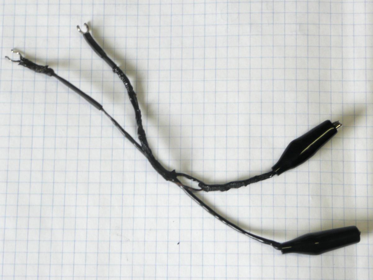
| Melted ground clips |
|---|
Bug 68: Evidently, one of the clips, which was supposed to be on Pin C (ground) of the backplane socket inadvertently came into contact with pin A (+10). The current flowed through the scope probes to the other ground clip, melting both ground clips (but fortunately, doing no damage to the probes or scope).
We ordered replacements, and extras, and the parts required to build new
ground clips that will end not in alligator clips but in insulated sockets that
push down over pins on the backplane, eliminating this risk.
|
|
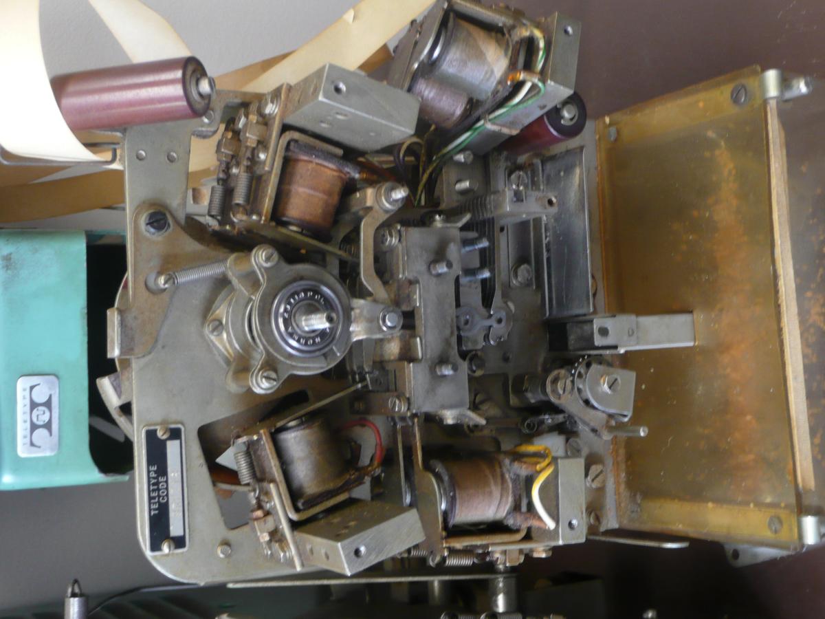
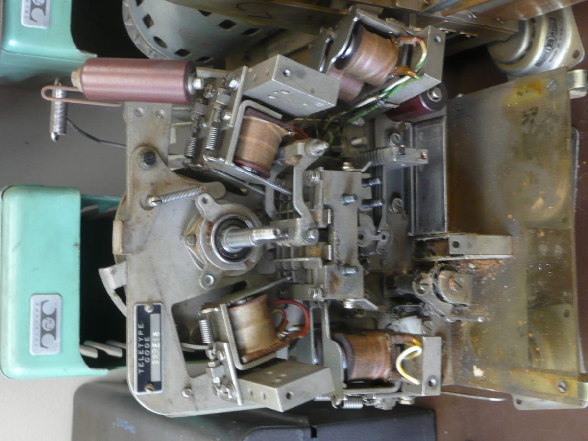
| Layer 3 | Layer 4 |
|---|
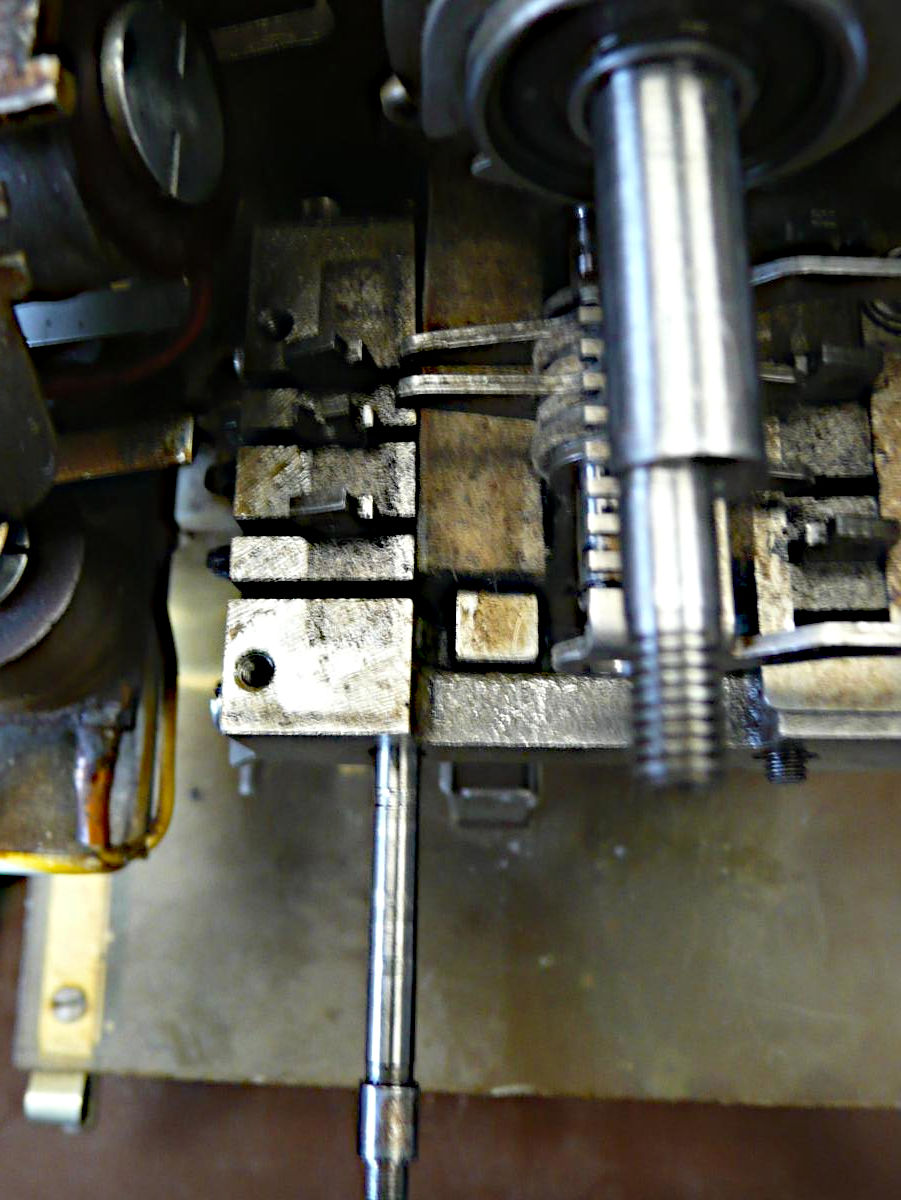
The mechanism parts that we must move from one punch to another are explained in the diagram on page 12 of High Speed Tape Punch (BRPE Type) Description and Principles of Operation, Teletype Corp. Section 592-802-100 Issue 4, July 1969. The exploded diagrams in the parts list are a helpful guide for assembly and disassembly, particularly High Speed Tape Punch (BRPE 6 and up) Parts, Bell System Practices Section 592-802-800TC Issue 2, June 1966, Figure 2, magnet and toggle mechanism. Unfortunately, these manuals do not suggest the order in which to remove parts to mine one punch for parts to install on another.
So, we have worked slowly inward from the front, removing parts one small layer
at a time, and placing each layer of parts in a small plastic bag along with
a tag indicating what punch it came from and the order of removal. The
photos here show the two punches, one with 3 layers removed, one with 4 removed.
|
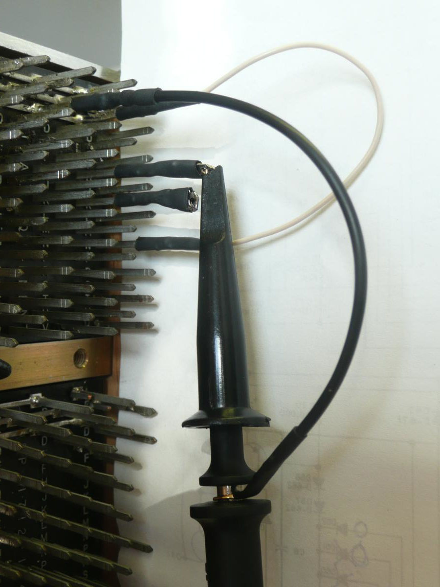
| Wire-wrap ground clips |
|---|
Note that grounding clips are commercially available that include push-on connectors for "modern" wire wrap pins that are 0.025" square, designed for 30 AWG wire. Our old pdp-8 backplane, however, uses larger pins designed for 24 AWG wire, so we had to make our own.
Molex 1501811020 connector sockets are desined go push onto .062" round pins that are intended for use in a broad line of Molex multi-pin connectors. These pins, as luck would have it, slide snugly onto the wire-wrap pins of the PDP-8 backplane.
We used these Molex .062" sockets to replace the alligator clips on two of the scope probe ground clips, with 1/8" heat-shrink tubing to protect the outside of the socket and provide strain relief. These should be safe to push onto backplane pins even when the power is on with no risk of shorting adjacent pins.
We also made two similar sockets that clip to the scope-probe tip to allow
secure and relatively risk-free cliping of the probe to wire-wrap pins and
we made a shorting jumper. We made the latter because the memory tuning manual
told us to short some backplane pins to ground for some tests and this seems
safer than using alligator clips.
|
| Removing pawls |
|---|
|
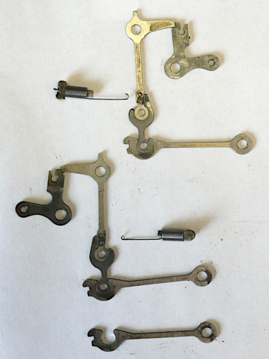
| Linkages to move |
|---|
During extraction of the parts, we noticed that the drag link for the sprocket track on the tape is a different part than the drag links (part number 143080) for the data tracks. This is explained in note 3 on page 3 of the parts list, where it says that a different drag link (part number 146678) is used for punches that have an advanced feed hole. Our 6-bit punches have this feature, but the 8-bit punch we want does not. So, we also extracted the extra drag link shown in the photo.
While going over the parts list, we discovered that both of our punches are missing the felt wick (part number 142849) that sits on top of the drag link pivot bracket (part number 142846). The clip that is supposed to hold this felt is present.
Having extracted these parts, we began reassembling the punch from which they
were extracted, in part so that we will have some practice on this complex
job before reassembling the punch we intend to widen to 8-bits.
|
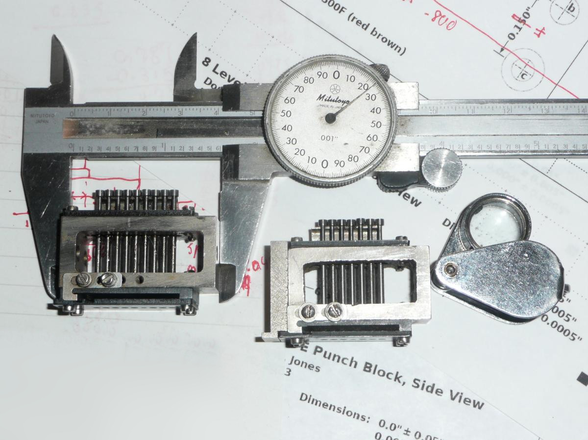
| Side view of blocks |
|---|
|
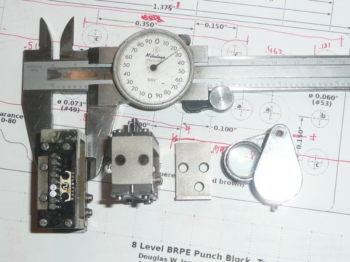
| Top and end views |
We noted some interesting differences between our 6-bit punch block and
Bob's 8-bit block. The most notable is that the cast-iron body of our
6-bit block shows the pebble texture of sand casting on the hollow of the block,
while the hollow of Bob's block has a machined surface. Evidently, the 8-bit
block was machined from a solid billet of cast iron.
|
|
|
Measuring the block was frustrating. It was very easy to make clerical errors, and locating centers of screw holes is particularly difficult. What seemed to work best was to measure to the screw head and then add half the screw head diameter. This only worked because Teletype Corp. used cheese-head screws with heads that are very concentric and very uniform in diameter.
To find the distance between two screw holes, the easiest solution was to measure the distance across both screws, including both screw heads, and then subtract the head diameter.
Note that any time you add or subtract measurements, the error in the result is the sum of the errors in the individual measurements. We found that we had to repeat measurements many times before we were confident that we had a useful value.
The drawings at the left are the result of this effort.

|
| All 8 drag links |
|---|
The first step in widening our BRPE punch to 8 bits was to remove the shaft on which the drag links pivot (part number 124847) and then replace the slightly over-length drag link for the advanced-feed hole punch on the 6-bit punch block and add the two missing drag links.
With the pivot pin removed, the springs on the long toggle arms pushed
the drag links left and right, and many of the lower short toggle arms
(part number 143079) fell out. They all fell out in the next step.

|
| Installing toggle arms |
|---|

|
| Toggle arms installed |
The problem was then to install or reinstall all 8 toggle long toggle arms
(part 143078)
plus the feed punch link (part 124279) that punches the sprocket holes
along with the felt washers (part 124244) that help space and oil these links. Because the shaft was inserted from the front, this involved working from
front to back. The first few parts were easy to install, but as work
progressed, the space became more and more congested. Needle nosed pliers
were essential, and installing the very last felt washer was frustratingly
difficult.

|
| All the links assembled |
|---|
The next step was to swing the lower toggle arm up to join with the upper toggle arm. Particularly at the back, this was difficult, as the lower arm had to be slid up between the teeth of the metal comb that aligns the linkages. We found that using jeweler's screwdrivers to prod things into alignment worked.
The comb teeth serve as spacers (part 124282) between the toggle joints, and the teeth are separated by smaller spacers (part 124300). All of these in front of the feed-punch-link were removed, and this linking the upper and lower toggle arms much simpler because the joint was exposed until the next comb tooth and spacer were slid into place.
Finally, with pieces assembled, it was time to tighten the nuts on the ends
of the posts supporting the comb. With these loose, the comb structure
sags noticably. Snugging everything tight was done in steps, making sure that
all the toggle and drag links moved freely at each step. The final photo
here shows the assembled result, although some of the felt wicks are out of
place.

|
| Expanded to 8 bits |
|---|

|
| Robbed for parts |
After reassembling the eccentric linkages that tie the punch bail to the main shaft, and after assuring that the whole mechanism moved freely, we set to work robbing two solenoid assemblies from our parts machine and mounting them on the widened 8-bit machine. Fortunately, when Teletype Corp. built our machine, they included all the necessary wires in the wiring harness, with the ends taped and neatly bundled where it was hard to find them. As built, the ends were nicely tinned, and the wires were cut to exactly the right length.
One tricky detail is the selection of the correct armatures for each solenoid. The parts list drawings show 3 variants, and all 3 were present in our punches. I turns out that the outermost punch on the 8-bit block nees the same broadly eccentric armature as the armature that controls the tape advance, part 142871.
The assembled result is shown to the left, along with the machine we robbed
for parts. You can see which solenoids we moved because the originals in the
widened machines have flat metal steel brackets while the moved solenoid
brackets are cadmium plated and have coined surfaces (a waffle texture).
We made one mistake in our reassembly. The solder terminals
on the solenoids need to be oriented down, not toward the front. We will
need to remove and reattach the solenoids to fix this.

|
| Assembled Correctly |
|---|
With all of the lubrication done, we finished reassembling the punch (save for
the 8-bit punch block we need to make).

|
| The motor running |
|---|
We will not run the mechanism under power until we have done some of the
preliminary adjustments.

| |
| Noise on MA0 |
|---|
The ringing disappeared when we put the G209 boards back in. The loading
provided by the boards appears to come quite close to providing ideal
termination for these lines. The noise was also damped when these lines
were loaded, and in any case, the noise does not approach the
switching threshold of the R-series logic.

| |
| MA11(0) on Dec. 9 | |
|---|---|

MA11(0) now |
|
Note that the two traces shown here were recorded using different horizontal
scales. The red trace in both images is taken from the same pin.

|
| Advancing tape |
|---|
Looking at how the linkages worked, we noticed that the feed blocking
pawl was not completely disengaging from the toggle extension of the feed
toggle linkage. As a result, the knee joint in the linkage always buckled
so the stroke in the feed pawl was insufficient to turn the feed ratchet.
(All of these mechanisms are described in Figure 9 of
High
Speed Tape Punch Unit (BRPE type) Description and Principles of Operation
Teletype Corp., Section 592-802-100, Issue 4, July 1969.
Moving the stop plate that limits the movement of the blocking pawls was sufficient to fix the problem. With this plate moved, pressing the feed-out lever caused the tape advance sprocket to advance one step per revolution of the main shaft.
At this point, we decided to take a risk and mounted 10 feet
of pre-punched tape in the mechanism (without a punch block) and turned
on the motor. The machine gives a constant 110 cycle-per-second buzz when
the motor is spinning, but it is well enough balanced that the chassis does not
vibrate too much. To our great satisfaction, the tape advanced at 11 inches
per second whenever we held down the feed-out lever and stopped promptly when
we let it up. The photo here shows the tape in motion, with the moving
parts and moving tape quite blurred.
Bug 64 and Bug 67: Having replaced all of the G209 boards and verified that the noise on the memory address lines appears to be acceptable on Apr. 7, it was time to test the memory. For a preliminary test, we toggled zeros into memory locations 0 to 7, and on reading, we always got zero back. Then, we toggled ones into locations 0 to 7 and got the following back; note that we repeated the experiment twice, toggling zeros into memory between attempts to store ones:
| address | trial 1 | trial 2 |
|---|---|---|
| 0 | 011100111011 | 011100111011 |
| 1 | 111110111011 | 111110111011 |
| 2 | 111010011111 | 111010011111 |
| 3 | 111010011011 | 111010011011 |
| 4 | 111110111111 | 111110111111 |
| 5 | 011110111110 | 111110111111 |
| 6 | 110100000010 | 111110010011 |
| 7 | 110010000010 | 110010000011 |
Of course, we had hoped for all ones, but we have never gotten any 1's back from memory before, so this represents tremendous progress. It looks like bit 5 never works, and bit 1 always works. The other bits are marginal, working sometimes.
Repeatedly reading the same locaiton slowly shifted the value toward 000000000000 because of the read-refresh cycle of the memory. Any bit that read as zero on any trial was written back as zero and stayed zero from then on.
Bug 66:
The G007 sense amplifier in MB27 handles bit 5 of every word. On
Nov. 20, 2024
we were unable to balance this sense amplifier. This problem may explain
why bit 5 never worked in our first marginally successful test of memory.

|
| BRPE wiring diagram |
|---|
The only difference that is possibly significant is that Figure 6-10 specifies 1N91 diodes, while our machine has 1N1693 diodes. The 1N91 is a germanium diode rated at 65V and 150mA continuous. The 1N1693 is a silicon diode rated at 200V and 0.6A continuous. The 1N1693 is a better choice in this circuit, but nowdays, the 1N4004 rated at 400V and 1A continuous would be a reasonable substitute.
Teletype's schematic is awkward to follow, and our drawing also gives the layout
of the face of the Amphenol socket (or the back of the plug that fits that
socket). This is a key detail needed to make a cable to connect here.

|
| 110 pulses per second |
|---|

|
| 250μs, 48V peak-to-peak |
Our measurements confirmed that our machine actually runs at 110 revolutions
per second, or about 9ms per revolution. The pulse amplitude given in the
above-cited bulletin is for an older style of magnetic pickup.
Our pickup matches the description in paragraph 3.03
High Speed Receiver Sets (BRPE) Description,
Teletype Corp. Section 592-831-100TC, Issue 1, Sept. 1969.
(This is part of a later edition of Bulletin 215B.)
This states that the pulse amplitude at this speed should be 40V peak to peak
with a maximum pulse width of 250μs using the same test circuit.
Our measurements show that the 250μs pulse width is measured
between the two peaks of the waveform, exactly as specified in the figure
just cited in the 1965 version of Bulletin 215B. The entire pulse is
closer to 1.2ms, including the rise to the first peak and the fall from the
second. Our machine has a peak to peak amplitude is closer to 48V.
Bug 71 and starting work on
Bug 72, reverse engineering the punch controller:
We spent some time with a multimeter tracing backplane wiring on the
controller for the paper-tape punch. This controller is packaged as part of a
perhipheral interface bundle. Our
preliminary tracing of wires shows that the DEC
Module Utilization List D-34D-0-3 Rev J
is indeed related to our machine but there are several differences. Our first
focus is on the socket (backplane location C32) for the cable to the BRPE
punch. From the actual wiring, we inferred the following:
Apr 21, 2025, Reverse engineer BRPE controller
| A | +10 | ||||
|---|---|---|---|---|---|
| B | –15 | ||||
| C | gnd | ||||
| D | V- | supply, to pin V of each W040 | |||
| E | sense | to ground | |||
| F | sense | to C20 pin R, with 0.01μF to ground | |||
| H | feed | to C28 pins R,S (W040 outputs) | |||
| J | hole 0 | to C31 pins R,S " | |||
| K | hole 7 | to C23 pins R,S " | |||
| L | hole 6 | to C24 pins R,S " | |||
| M | hole 5 | to C25 pins R,S " | |||
| N | hole 4 | to C26 pins R,S " | |||
| P | hole 3 | to C27 pins R,S " | |||
| R | hole 2 | to C29 pins R,S " | |||
| S | hole 1 | to C30 pins R,S " | |||
| T | nc | ||||
| U | nc | ||||
| V | nc | ||||
| Backplane slot C32 | |||||
Note that the above is tentative because we have yet to trace the data back to the PDP-8 I/O bus so we are not certain of the bit numbers. The module utilization list does assign the feed solenoid to the W040 C28, but it assigns the 8 data bits quite differently. Note that we have found a description of the PDP-7 BRPE cable embedded in Drawing BS-D-KA71A-0-A in the PDP-7 Maintenance Manual, F77A, Digital Equipment Corp., 1966. The pinout we infer from our wiring is compatable with that cable using a W023 connector, except that our machine does not support the motor-start signal to the punch found on the PDP-7, nor feedback for paper out.
The W040 solenoid driver is rated at 0.6A, and the data sheet allows them to be used in pairs to drive 1A loads. Teletype's Bulletin 215B: Technical Manual, High Speed Tape Punch Set (BRPE), Teletype Corp., Mar. 1965. Says our unit requires 1A, 28V, 4.5ms pulses. The 1.2A capacity of the W040 driver pairs offers an adequate safety margin, particularly considering the 50% duty cycle.
The backplane utilization list shows the sense line going to an input of a
W520 comparator
in slot C20. This would work with Teletype's older BRPE pickup
coil that only gave a 6-volt timing pulse. The W520 cannot handle the almost
50V timing pulses we measured on
Apr 17.
We have yet to examine enough of the
additional wiring to determine if that slot is actually wired for a W520.
Note that the
W500 high impedance follower
would be the correct device to take input from our BRPE pickup coil.
Bug 72: Where DEC's Module Utilization List D-34D-0-3 Rev J, Digital Equipment Corporation, 1967 shows a W520 comparator in slot C20, the wiring of our backplane is not consistent with that board. Instead, our backpane is wired for a W501 Schmitt trigger. This board includes the option of running the input through a 330Ω 6.8μF RC integrator before the Schmitt trigger input, and the trigger thresholds can be set from 0 to –2.5V (with values of 0V, –0.8V and –2.2V easily selectable by backplane wire-wrap jumpers without other components).

|
| Effect of W501 integrator load |
|---|

|
| Output of W5O1 integrator |
First the 330Ω resistor in the integrator significantly loads down the BRPE sync-pulse, dropping the peak-to-peak amplitude from the 48V we measured on Apr 17 to about 21V as shown in the upper trace here. The pickup coil in the BRPE magneto has a 100Ω resistance, and our wire of wire no-doubt introduced further impedance.
Second, the integrator output is a clean 1.4V negative pulse, as
shown in the lower trace.
This is within the operating range of the Schmitt trigger and switching
thresholds of 0.6 and 1.2V would be work to produce clean output pulses.
Bug 64: Looking at drawing RS-B-G007 Sense Amplifier, it is apparent that the DEC G007 sense amplifier consists of several logical sections:

|
| Bit 3 sense amp out |
|---|

|
| Bit 4 sense amp out |

|
| Bit 5 sense amp out |
The scope traces shown to the left are all triggered on the memory strobe signal, shown in blue. The signal from pin J of each sense amplifier is shown in blue.
In the traces for bit 3 and bit 4, we are reading (mostly) ones, and the sense amplifier has a strong output that closely overlaps the strobe signal. This is what we expect.
Bug 66:
The trace for bit 5 is more problematic.
The sense amplifier seems to be working pretty well. It sees a signal during
the write cycle as the contents of memory are refreshed. What is missing
is any response coincident with the strobe during the read cycle. Is there no
one in memory? That could be because the inhibit drivers are not driving the
inhibit line, or, worst case, that the inhibit line is broken.
Bug 66: On May 5 we arrived at a worst-case hypothesis that the inhibit winding for bit 5 might be broken. So we measured the resistance of all of the inhibit windings. We measured these at the inhibit driver outputs, so this takes into account the full wiring path from inhibit driver to core stack as well as the wiring within the core stack.
All of the inhibit windings measured between 13Ω and 14Ω with the G208 inhibit driver boards in place. The schematic for these boards shows an 82Ω resistor on the board in parallel with the inhibit winding plus other electronics. Pulling one of the boards allowed us to measure the resistance of just one of the inhibit windings as 16Ω.
These measurements effectively rule out the worst-case hypothesis. Whatever is
wrong with bit 5 is not a broken inhibit winding in the core stack.

|
| Paper-tape punch controller wiring |
|---|

|
| Backplane reverse-engineering form |
|---|

|
| Backplane wiring, as we found it |
|---|
There are two significant changes here from the Module Utilization List D-34D-0-3 Rev J, Digital Equipment Corporation, 1967. First, no wiring from the paper-tape punch subsystem connects to slot C14. DEC's list shows it holding something involved with a feed switch. Presumably, pressing the feed switch would cause the punch to spit out a tape of all NULLs as leader. Our machine has no provision for a feed switch, and the wiring from slot C14 leads to other parts of the larger backplane.
Second, DEC's list shows a
W520 comparator
in slot C20 where our backplane is wired for a
W501 Schmitt trigger, although no board is in that slot.
Finally, the map shows a different relationship between the
W040 solenoid drivers
in slots C23 to C31 and the punch pins. Our wiring connects the two drivers on
each board in parallel to one punch pin, while DEC's list seems to indicate
pairs of drivers on adjacent boards being paralleled to each pin.

|
| Type 75 controller, as found |
|---|
Things were more complex in the lower part of the drawing for two reasons. First, the PDP-7 device interface included provisions to automatically power up the BRPE punch on demand and power it down after a period of inactivity. There is no evidence that our PDP-8 BRPE controller could ever do this, although later revisions probably did so.
Second, the Psychology department changed their Type 75 controller to control
some kind of Tally paper-tape punch. They removed some wires to do this and
added 3 wires and a small capacitor. Their design, as we have re-drawn it here,
makes sense for open-loop control of a punch where each punch cycle consists
of outputting 9 parallel punch pulses (8 data, one feed) and then waiting an
unknown interval before allowing the next punch cycle.

|
| Type 75 controller, as needed |
|---|
First, the BRPE punch requires closed-loop control, synchronizing the punch output pulses with a strobe pulse returned by the punch. The original wiring is for a 6-volt strobe pulse, but our BRPE punch produces a 20 volt pulse. The drawing shows the input integrator of the W501 Schmitt trigger used to drop the voltage. We tested this on May 1. The next step is to use the Schmitt trigger to generate a clean Punch-Ready pulse from the strobe. We tried to test this and found a bad transistor in our only unmodified W501 board, creating Bug 73.
Second, if the leading edges of the Punch-Ready and Punch-Active signals reach the and gate that triggers the first R302 one-shot to produce the Punch-Start signal with the wrong timing relationship, the output pulse of the first R302 may be malformed (the probability is low). This, in turn, has a low probability of triggering a malformed Punch-Feed pulse, which could cause the punch to mispunch data. This problem is fully documented in Designing Computers and Digital Systems Using PDP 16 Register Tansfer Modules, C. Gordon Bell, John Grayson and Allen Newell, Digital Equipment Corporation, 1972. pages 256-258.
We think DEC used two one-shots in series to solve this problem here. Later models of the same controller may have used a simple and gate, but as Bell, Grayson and Newell point out, this is an intractable problem. No digital system has ever been developed that can, with 100% success and in strictly bounded time, break timing races between inputs that come from independent sources. There is always a small probability that the inputs will appear simultaneous, and if that occurs, it can put any know digital system into a metastable state. The most we can do is either release the bound on deciding which input came first (the CSMA-CD protocol for Ethernet does this) or we can make the probability of a metastable state arbitrarily small by adding gain to the system. Our guess that DEC used a 100ns one-shot in front of a 5ms one-shot is an example of lowering the probability.
Bug 71:
The proposed Type75 BRPE controller schematic given here includes a schematic
for the cable to the BRPE punch. We have included the (untried) option of
having the cable automatically turn off the punch when it is out of tape,
and we believe that, with the W501-Schmitt-Trigger thresholds set as suggested
to 0.0V and -1.4V, the Punch-Ready signal will not be asserted until the punch
motor is almost up to speed. We need to try both of these before we can be
sure they will work.

|
On the W501 board the Psychology department modified, the capacitor C1 had
been replaced, a resistor had been added, and in the process,
they tore one foil trace on the board. We undid all of this, including
replacing the 6.8μF 35V Tantalum Capacitor with an old one that had a
quality-control date code in the early 1960s.

|
Our measurements on May 1 Suggested that Schmitt-trigger threshold voltages of 0V and –1.2V ought to work with the integrator output when fed with Punch Sync. Inspection of the oscilloscope trace given to the right shows two things. First, our board repair worked, and the 70-year-old capacitor we used was good. Second, the thresholds we chose were barely acceptable.
Finally, DEC's advertised thresholds for the W501 are only approximate. Connecting pin L of the W501 to ground does not set the upper threshold to exactly 0V, it sets it to something like –0.15V, and connecting pin M of the W501 to a measured –1.2V sets that threshold to about –1.35V, just short of the negative peak of the integrator output on the board we tested. Given that C1, the capacitor in the integrator, has a 20% tolerance, this is not a reliable design. We will have to switch to a threshold closer to 1V (probably a nominal 0.8V).
Finally, we tested the power-on and power-off behavior of the circuit.
Having a threshold precariously close to the peak voltage does not prevent the
one-shot from firing when the flywheel is spinning very slowly. The integrator
acts as a low-pass filter, and at the lowest speeds of the flywheel, the
magneto that produces the sync pulse puts out a few volts as frequencies far
enough below the cut-off frequency that these get through to the Schmitt
trigger. As the motor accelerates, low-pass filter behavior wins out over
the increased voltage of the magneto output, so during most of the spin-up,
the Schmitt trigger produces no output until the magneto is up to speed.
The good news is that the integrator output never exceeded the -10V to +10V
range that the W501 is advertised as being able to accept.

|
The diode we replaced is labeled D11 in the map to the right. According to
Drawing RS-B-G208
in the Maintenance Manual, D11 is a flyback diode protecting Q3, the
first-stage drive transistor for the inhibit driver that handles bit 4.
This would reduce but not eliminate the drive current to the second-stage
transistor driving the bit-4 inhibit pulse.
Bug 73: As we noted on May 21, we have a W501. board with a bad transistor. None of the transistors on that board match the W501 Schematic but testing with an ohm meter showed that Q1, Q2 and Q4 are, at least, NPN transistors, as specified. Q3 appeared to have a bad junction, and on very close inspection, we found that it was marked 2N3393. This is also an NPN transistor, while the DEC999 part specified in the schematic is a PNP transistor. Inspecting the solder side of the board showed no evidence of rework, and the component side had the usual number of quality-control stamps to assure us that the board had been tested at the factory. Evidently this board represents a factory assembly error and quality-control failure.

|

|
| –1.5V Lower Threshold |
|---|

|
| –0.8V Lower Threshold |
As with our tests on the other W501 board on May 28, our tests show (again) that the nominal upper threshold of 0.0V gives an actual threshold closer to –0.15V, and a nominal lower threshold of –1.5V is actually closer to –1.35V.
This repeatability between boards with very different histories, different transistors and a replaced capacitor is encouraging. The fact that the integrators produced almost identical peak voltages just shy of –1.4V is also good, but with both boards, a nominal lower threshold of –1.5V is perilously close to the peak of the pulse.
Fortunately, the second board works well with a nominal lower threshold of –0.8V. The measurements shown here show that this gives an actual threshold closer to –0.65V. This is the design we will use when we connect the BRPE punch to the PDP8.
Bug 66: We had time to go back to the PDP-8 memory problems. Swapping the G208 inhibit drivers in backplane slots MC24 and MD24 did not change the problem with bit 5 in memory. This should have moved the problem to a different bit, so we know the problem is not in the inhibit drivers.
We used our logic probes to verify that data flows from the switches on the front panel through the memory data registers to the inhibit drivers.
Finally, we swapped the G007 Sense Amplifiers in backplane slots MA27 and MB27. This moved the problem with bit 5 to bit 4, proving that the biggest memory problem is indeed tied to this sense amplifier.
Given that we already went over this sense amplifier checking things with an ohm meter on May 17, 2019, and given that our tests on May 5 show that this sense amplifier is amplifying something, we decided to pull the bad sense amplifier and build a bench test rig for it. This also requires pulling the G008 Master Slice Control board because this generates 3 reference voltages used by the sense amplifier.
We started jumpering two backplane slots to build a bench-test rig for
these boards, but we need to do a little research to figure out how to fake
the input from the core memory sense winding before we turn on the power to
test this board. We suspect that the "fake" sense winding will involve a loop
of wire through a ferrite core to couple it with the signal generator output
of the scope, an output we have never used before.

|
We used a ferite core to couple to the sense input, with 9 turns on the signal
generator side and 1 turn connected to the sense input. We adjusted the signal
generator to produce a square wave with a pariod of 15μs and an amplitude
giving 8mV on the single-turn output side of the core.

|
| In (blue) and stage 1 out (red) |
|---|

|
| In (blue) and stage 2 out (red) |
With the single-turn output of our core connected to the sense input of the
G007 board, we followed the signal through the board.
The outputs of Q2 and Q5 look good. These are the first and second stages of
the differential amplifier.
They are complementary transistor pairs, so there are two output traces for
each, one signal being the inverse of the other. The first stage amplifies the
8mV test signal to 40mV, and the second stage brings the amplitude up to about
250mV (0.25V). This indicates that Q2 and Q5 are both good.

|
| In (blue) and stage 2 DC out (red) |
|---|
The scope traces shown above were AC-coupled, so the DC component of the signal is invisible. Looking at the DC component, shown in the scope trace to the right, note that the output signals from Q5 have a DC offset of about 7.3V. These two outputs drive Q7 and Q8, emitter followers connected in parallel to combine the two sides of the differential signal, effectively computing the maximum of the signal and then comparing that maximum (via Q9) with the "slice" voltage.
We got no signal on the emitters of Q7 and Q8, suggesting either that these
transistors are bad or that Q9 is bad. Q7, Q8 and Q9 are DEC-2894
(equivalent to 2N2894) transistors, so we need replacements before we proceed.
|
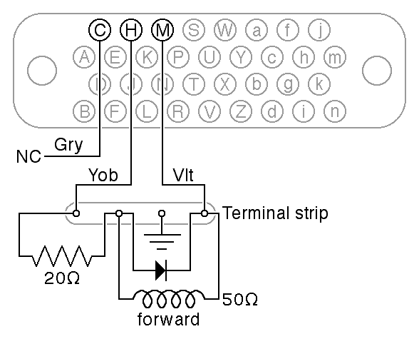
| Tape Advance Wiring (modified) |
|---|
Since we know we will need to build a new cable, it seemed appropriate to bring the wiring of the reader closer to that documented on page 8 of the Tally 424 manual. As we received the reader, there was no reverse coil, but the connector wiring for the reverse coil (pin C) was connected to the forward coil. We changed this so the wire from pin C was not connected and instead, pin M, as documented in the manual, was connected to the forward coil.
The Tally reader documentation (and the nameplate) say that the coil resistance is 50Ω and it is designed to operate on 24V pulses. The wiring apparently added by the psychology department includes a flyback diode and a 20Ω series resistor. This resistor should allow the coil to be safely driven by 33V pulses. The BRPE punch, in comparison, is designed for 28V pulses.
While we were checking the reader, we verified that the other wiring conformed
to the manual and the reverse engineering efforts we started
on Jun 2, 2014. All this work is
in preparation for reverse engineering the (highly modified) Type 750C
high-speed paper-tape reader interface.