
The University of Iowa's DEC PDP-8Restoration Log
Part of
the UI-8 pages
|
The University of Iowa's DEC PDP-8Restoration Log
Part of
the UI-8 pages
|
This is a chronological log of the progress restoring the University of Iowa's PDP-8 computer. Entries are added at the end as work progresses. Click on any thumbnail image to see full-sized image.
|
|
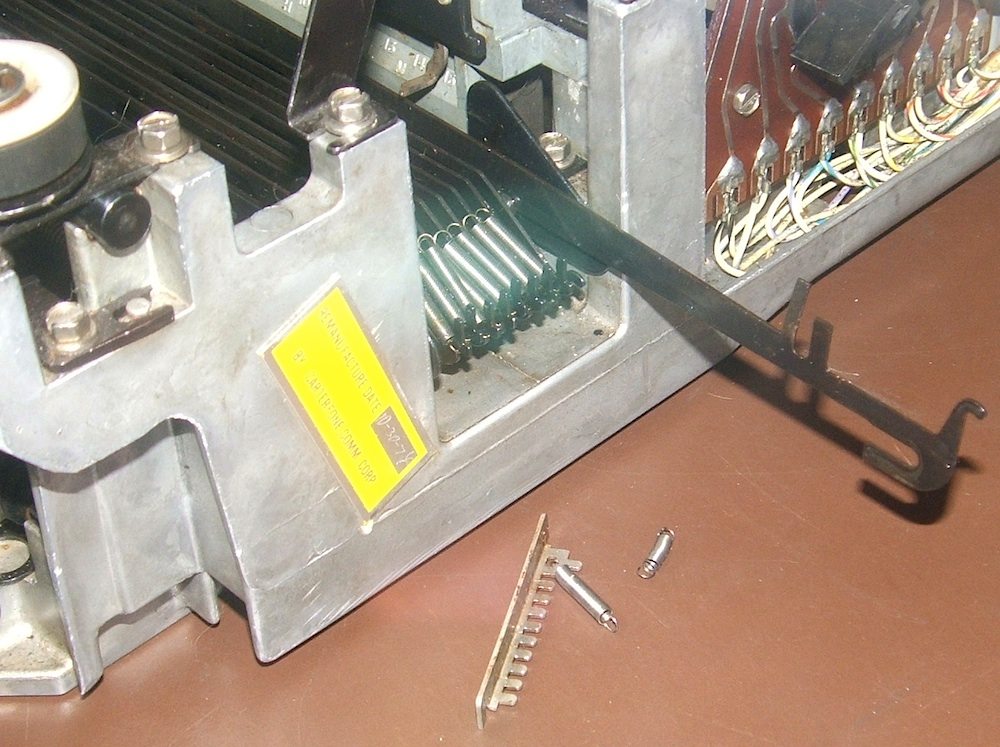
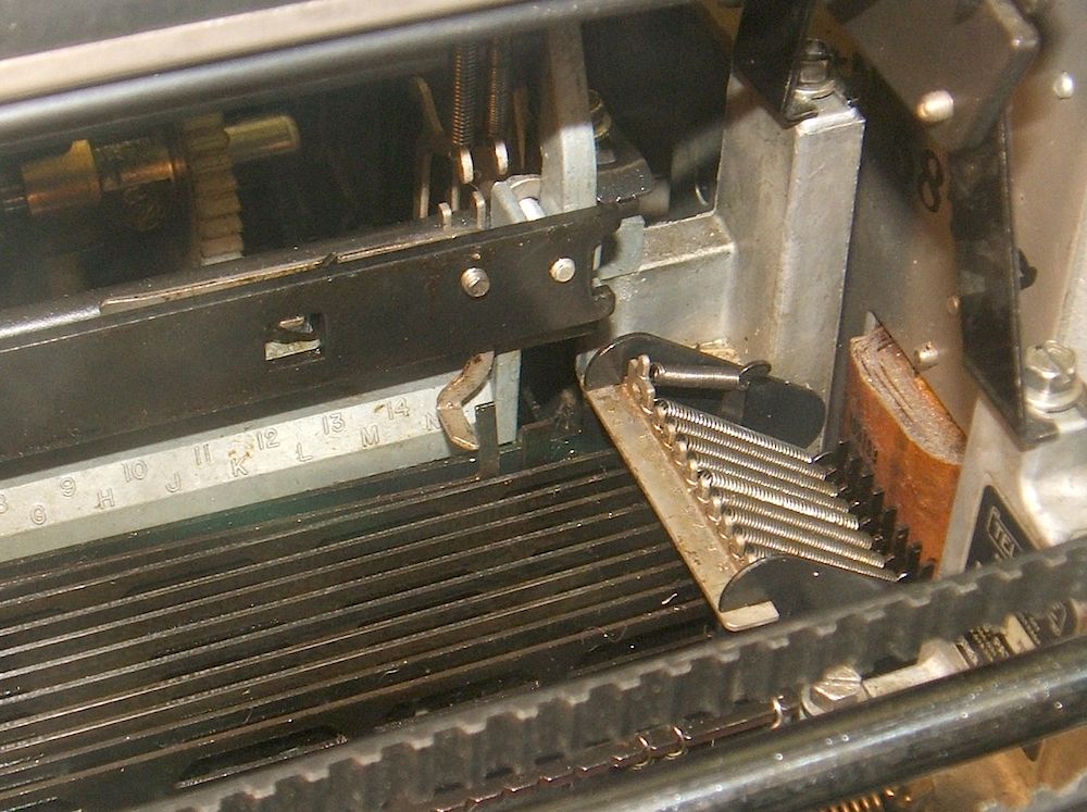
| Removing a codebar | Codebar fixed |
|---|
With the codebar in the right position, as shown in the second photo,
and with the typing unit reinstalled in its
place, the bell only rings when Control G is typed or the carriage reaches
near the end of its travel. So, this problem is solved.
We verifyied that we could type:
ABCDEFGHIJKLMNOPQRSTUVWXYZ0123456789
THE QUICK BROWN FOX JUMPS OVER THE LAZY DOG
Having done so, we loaded blank paper tape in the punch and tried punching the same message. The result looked good until we punched codes that involved 6 or more one bits, and then all of the punches failed to penetrate the tape.
Bug 52: Obviously, the punches were not quite punching deep enough, so we sought out the instructions for adjusting the punch penetration. These are documented on page 105 of Section 574-125-700TC of the Technical Manual (paper tape punch adjustments).
This specifies a gap of 0.017 to 0.037 inches. Measuring the gap, we found we were closer to 0.040 inches.
This is a very frustrating adjustment because access to the screw that must be loosened and then tightened is almost impossible with the punch mounted on the typing unit, yet the instructions for doing the adjustment begin with "set up an all marking code combination ... manually rotate the main shaft ..." — instructions tha can only be followed with the punch mounted on the typing unit.
Fortunately, a quick rummage in the toolbox found a ratcheting right-angle screwdriver. Even this did not fit when a bit was installed, but it uses bits with a 1/4 inch hex shaft, and fortunately, the screw in question has a 1/4 inch hex head. Using the ratchet driver as a wrench, we were just barely able to loosen it, reposition the pivot shaft, and re-tighten it, using a 0.025" feeler gauge to set the required gap, and then verifying that it was in spec by testing the gap with a 0.023 feeler gauge.
With this adjustment done, we were able to punch the entire ASCII character
set — or rather, the subset supported by this teletype, from NUL to Z,
as our machine does not have keys for square braces or backslash.
Bug 48: We punched a paper tape containing the following two lines of text, with CR and LF at the end of each line:
 !"#$%&'()*+,-./0123456789:;<=>?@ABCDEFGHIJKLMNOPQRSTUVWXYZ[\]←↑
THE QUICK BROWN FOX JUMPS OVER THE LAZY DOG
Note that the ← and ↑ characters are from the archaic version of ASCII supported by the Teletype Model 33. The modern characters for these are underline and circumflex. We made a typo in the tape, transposing these two characters. The first line is all of the printing characters supported by the Teletype in order of ascending ASCII character codes.
|
|
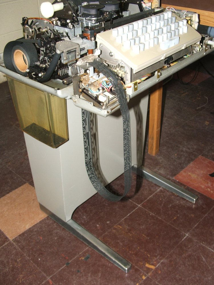
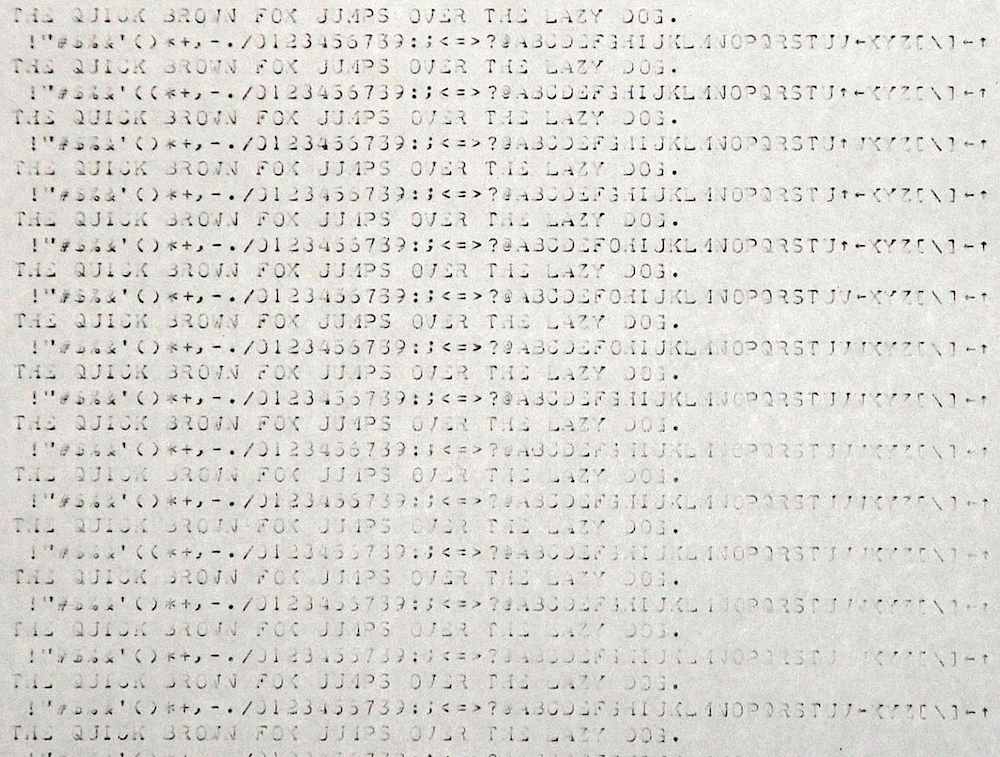
| Paper-tape loop | The test output |
|---|
Bug 59: The print contrast on the output is rather poor. We wonder if the platen needs reconditioning to help with this. The other defect in the printing we note is that the letters on the left end of the line are slightly darker on the bottom, while the letters on the right end of the line are slightly darker on top. Fixing this will involve slightly raising the left end of the platen and lowering the right end. Both of these are very small adjustments.
Bug 63: (Note added in retrospect.) The paper-tape reader only worked if we manually held down the clutch-trip magnet armature. See illustration on page 6 of Section 574-124-700TC of the Technical Manual (paper tape reader adjustments). At the time of this test, we did not understand why this was needed, but it worked adequately for extended testing.
Bug 58: If you zoom in on the test output, you will see that the output is almost correct except that, in the alphabetical sequence, but not in the text, V sometimes prints as ↑ and W sometimes prints as ←. The 7-bit ASCII codes for these, with bit 8 set to 1 (mark partity) are:
V 11010110
↑ 11011110
W 11010111
← 11011111
The Teletype transmits the least-significant bit first, prefixing each
code with a 0, the start bit, and adding 2 stop bits, both 1, at the end.
As a result, a string of W characters will be transmitted as follows,
shown with the actual data for each character in bold-face:
01110101111011101011110111010111101110101111
|
|
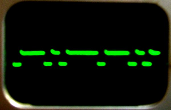
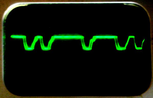
| Loop current 0111010111101110101 | Magnet current 1101011110111010 |
|---|
The figure captions above show the string of ones and zeros corresponding to
the data on the face of the oscilloscope. In each case, th data is, as
expected, a substring of the long string shown above. The only serious question
we have is whether the distorition in the current to the selector magnet is
significant enough to cause the first zero bit in the closely spaced pair
of zeros to be misread as a one. This does not seem likely, so we conclude
that our problem is most likely mechanical.
Bug 58: We needed to find out where in the receiver hardware bit 4 was being misread. The data path from the selector magnet, where we knew the data was correct as a result of the work done on March 7, to the data bus (the codebars) where we could easily see the misreads is complex, as documented on hand-numbered page 24 in the Teletype Model 33 and 32 Training Manual B-52 published by the General Telephone Co. of Ohio (undated). In summary:
Knowing that the codebar was moving does not tell us where in this chain of parts the data was being misread.
So, we used an iPhone to record slow-motion video of the very hard to see mechanism from several perspectives while holding down the repeat key and the W key, making sure that our videos recorded points where the W was misprinted as well as points where it was correctly received.
We then examined these videos using Apple's iMovie, playing them back at
half speed (even slower motion) and cropped to show just the mechanisms we
wanted to examine.
Bug 58: Examining the slow-motion videos made on March 23, we concluded that the selector magnet armature was being misread by the selector levers because the armature was being blocked from moving by the spacing locklever. That is, the fundamental problem is a timing problem where the lock lever is rising (blocking armature movement) just a little bit too soon.
On July 20, 2016 we had adjusted the Teletype's range finder to 60, with reasonable results. Now, we understand that this adjustment was not quite right, so we shifted the range finder from 60 to 65.
The results were perfect. In running off half a page of the "torture tape" we prepared on March 7, we saw no errors. So, we declare the printing mechanism to be fixed.
Tere is work remaining to be done on the Teletype:
Bug 61 and Bug 64: We powered up the PDP-8 (the hours meter reading was 26881.2) and toyed with the front panel switches to see what worked and what did not. We observed that the memory was not working, and at one point, we hit the run switch, causing the machine to fetch from successive memory locations. Because of the memory problems, the only opcode it fetches is 000 (with the AND light on the front panel shining brightly and the other 7 opcode lights out). We would expect this to roll through all 4K possible values of the program counter. Instead, we saw a different pattern in the PC bulbs:
Half intensity bulbs indicate that the corresponding bit is on as frequently as it is off, flickering too fast to be seen by the naked eye.
|
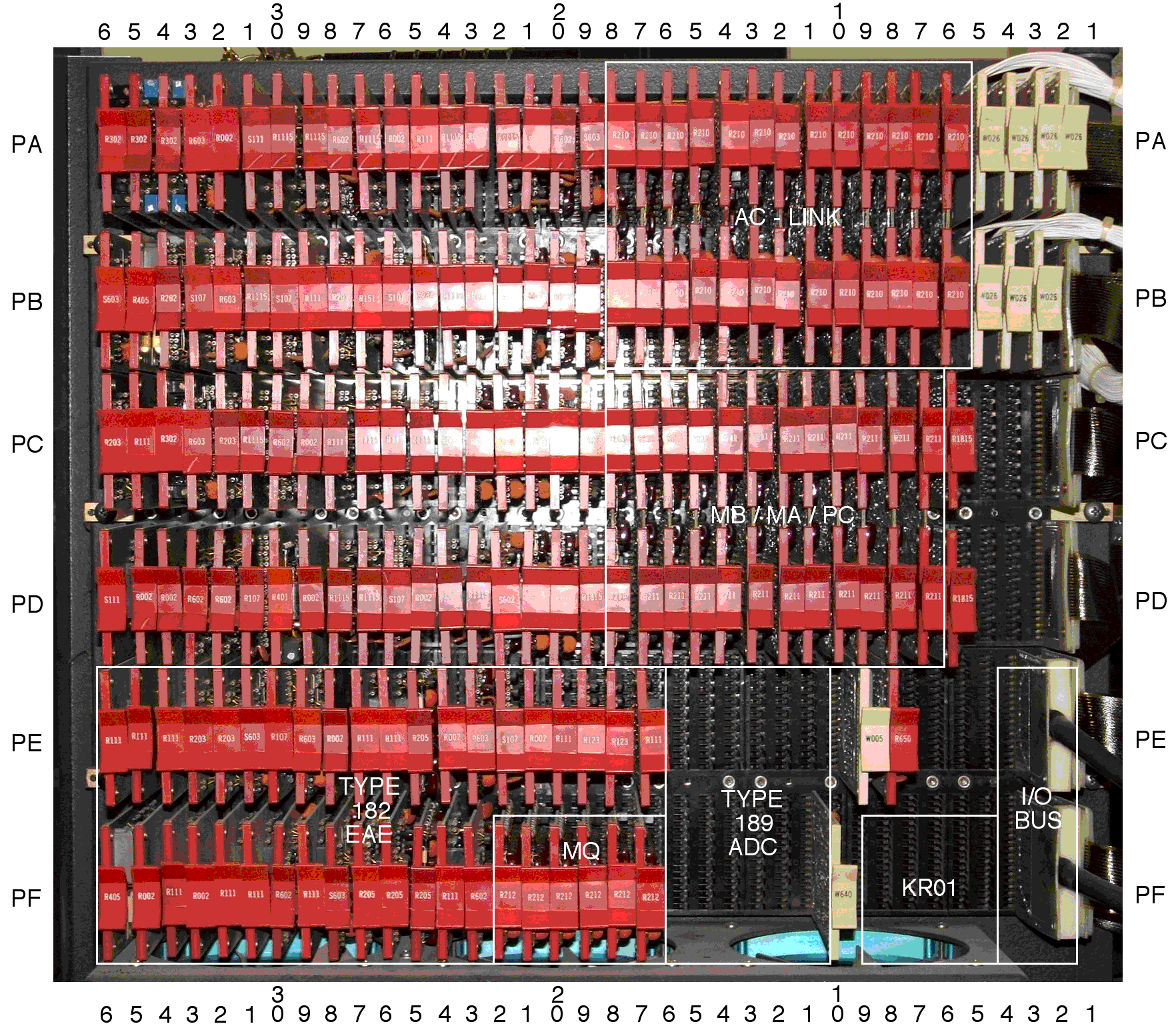
| Map of CPU half backplane |
|---|
Bug 49: We observed the final result above, confirming that the problem was with the carry in to the board now in position PC7 and PD7. This is the board we repaired on Sept. 30, 2015, so Bug 49 is reopened, and we need to resurrect the reverse engineering done for Bug 50. We replaced the tag on that board with a tag indicating the newly discovered problem.
After powering down the PDP-8 after these experiments, the hours meter
reading was 26881.4.
Bug 49 and Bug 61: Using an ohmmeter, we checked all the diodes involved in the DCD (diode-capacitor-diode) gates used to steer data into the PC on the suspect R211 board. One of them was shorted. Replacing this diode fixed the problem. Putting the board back into the PDP-8 and hitting the CONT (continue) switch on the front panel, all bits of the PC now glow, indicating that carry now propagates through all 12 bits.
However, our next test of the PC was to set the switch register to all ones
and then load the PC. A different bit did not load reliably. In fact,
repeatedly hitting the LOAD ADDR switch to transfer the switch register to the
PC caused this bit to toggle. Swapping the suspect R211 board to a different
location moved the problem to a different bit, so we know that board is also
bad. Scanning the diodes on that board located a bad diode elsewhere on the
board, but unrelated to the problem with the PC.
Bug 25 and Bug 59: In preparation for trying to make a short video on how the Teletype works, Tessa Walsh and I decided to try to improve the print quality. We removed the platen so we could take it outdoors and wash it with harsh solvents. To remove the platen without disturbing much else, we removed the right end plate (part number 181052) that supports the platen. This involves removing the two screws that hold the end plate to the bar (part number 181055) behind the platen and loosening the two height-adjusting screws at the bottom of the plate that link it to the right bracket (part number 181037). (See page 2, Section 574-122-800 of Teletype Bulletin 1184B, Parts, Model 32 and 33 Page Printer Set.) With these screws taken care of, the right plate pulls up and off to the right, allowing the platen to be pulled out to the right.
Rubbing alcohol removed all the ink residue from the platen, leaving us with black paper-towels, but the surface remained polished and faceted in the areas that had been intensively pounded by printing. WD-40 had little impact on the platen, so we decided to try truly harsh chemistry. A mixture of Goo Gone and acetone seems to have worked without harming the rubber. The paper towels we used came away only slightly gray, but all the shine was removed from the platen and the faceting was much less pronounced. It looked good enough that we decided not to try DOT 3 brake fluid (Suggested by Richard Polt) or other strong chemicals.
With the platen clean, we noticed that the pressure roller (part number 181044) was not free to rotate on the pressure shaft (part number 181054). (See page 3, Section 574-122-800 of Teletype Bulletin 1184B, Parts, Model 32 and 33 Page Printer Set.) The pressure roller appears to be made of some kind of hard plastic, so we cleaned it with alcohol and pushed a wad of alcohol-soaked paper towel through the hole. Cleaning made no difference, so we opted to ream out the hole just slightly, using the bur on the end of the pressure shaft to scrape the inside of the hole, removing just a dusting of plastic, until the roller spun freely on its shaft.
Bug 52: With everything reassembled, we set about re-adjusting things. The key test here is to type text on the left and right sides of the carriage. If the text is too black on top, that end of the carriage needs to be lowered. If the text is too black on th bottom, that end of the carriage needs to be raised. Letters like H, M, X and W are excellent for testing this.
We immediately noticed that all of these letters were printing too darkly on the right side, so we began by re-doing the left-to-right adjustment of the type-cylinder. Page 65, Section 574-122-700TC of Teletype Bulletin 310B, Vol 2, Technical Manual 33 Teletypewriter Sets covers this.
Vertical type alignment depends on the vertical position of the platen. This is adjusted by raising and lowering the two end plates that support the platen. Pages 109, Section 574-122-700TC of Teletype Bulletin 310B, Vol 2, Technical Manual 33 Teletypewriter Sets covers this. Working on the right side first, we used a screwdriver as a wedge in the pry point, loosening the vertical positioning screws, gently sliding the screwdriver in or out, and then tightening the screws between tests.
|
| Adjusting platen height and prelude to disaster |
|---|
|
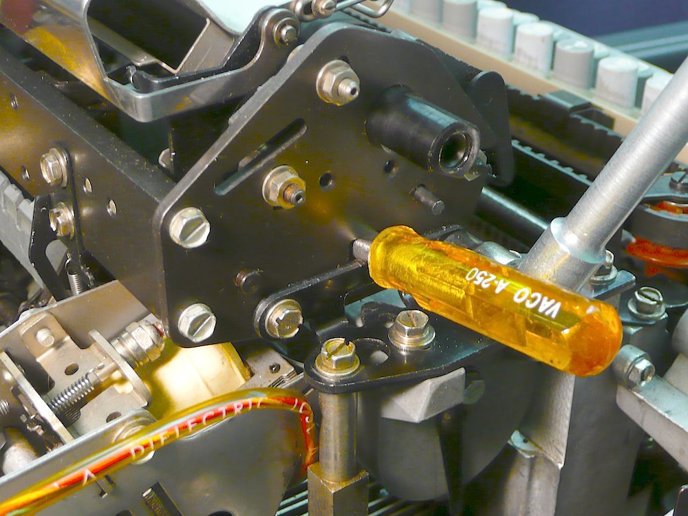
| Adjusting LF drive link |
|---|
|
| Adjusting LF up stop |
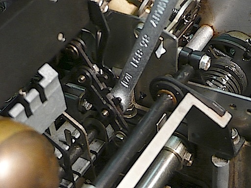
The drive-link adjustment is documented on page 115, Section 574-122-700TC of Teletype Bulletin 310B, Vol 2, Technical Manual 33 Teletypewriter Sets. This requires loosening two clamp screws that are only accessible from the side, with about 1/4 inch of clearance between the upper screw and the up-stop bracket, and about 1/2 inch of clearance between both screws and the right side plate of the selector mechanism. The socket wrenches we have been using will not fit in this tight space, but I borrowed a 1/4 inch combination wrench from the Engineering library that gave us a chance of loosening the clamp screws.
The box end of the combination wrench worked well on the lower clamp screw, but it was too thick to get between the up-stop and the upper clamp screw. The photo shows it engaged there. The box was too thick to fit past the up-stop bracket and engage the upper clamp screw, but we did manage to get the open end of the wrench on the upper clamp screw and loosen it a fraction of a turn.
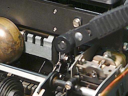
The up-stop adjustment is documented on page 114, Section 574-122-700TC ofTeletype Bulletin 310B, Vol 2, Technical Manual 33 Teletypewriter Sets. The mounting screws for the up-stop bracket are on the back of the bar behind the platen and are comfortably easy to access. I used a ratcheting socket wrench on these screws, seen in the second photo.
Unfortunately, both of these adjustments require examining the clearance
at points deep in the mechanism which are extremely difficult to examine.
In the end, I made these adjustments blind, simply shortening the drive link
by a small amount and raising the up-stop by a small amount, until the linefeed
mechanism only did a linefeed when required. After two tries on the up-stop
bracket, the line feed appears to work correctly.
Bug 63: On Mar. 7, we discovered that the teletype's paper-tape reader only works if we manually hold down the clutch-trip magnet armature. We have been living with that restriction, but today, I began reading two documents, the Schematic Diagrams and DEC's Teletype Modifications, Drawing LT-33, 1970.
As a result of this reading, I concluded that the paper-tape reader should
run in local mode, even with the addition of DEC's reader-run relay. Therefore,
something must be wrong with the wiring, probably something involved in the
wiring changes when we installed the reader-run relay back on
May 1, 2014.
We need to trace this out!
Bug 63: An anonymous person combined the information from Schematic Diagrams with DEC's Teletype Modifications in Drawing LT-33, 1970. The result is a convenient hand-drawn schematic entitled TTY READ CONTROL 4915-C that appears on the back side of the title page of some copies of the schematic, for example, this version.
The reader-run circuit is powered at 120VAC, so I used an ohm meter with one leg connected to the hot prong of the power cord, touching other points along the circuit. This allowed me to verify that the line-local switch does bypass the reader-run relay in local mode, and that the distributor trip magnet is correctly wired (called the "step-coil" in the hand-drawn schematic).
|
|
| Bad contact placement | Fixed |
|---|---|
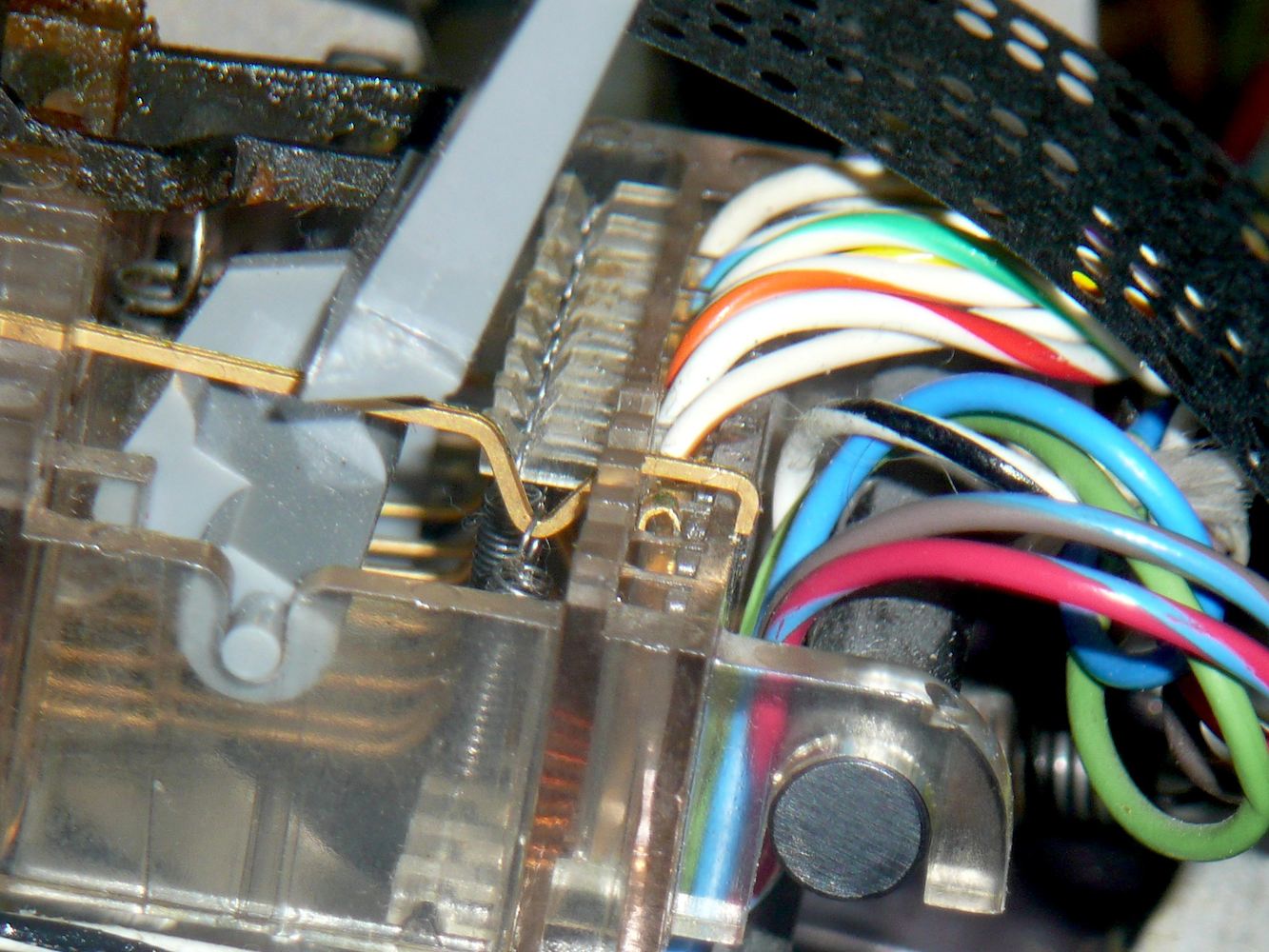
| Close-up view from the tape reader's left | |
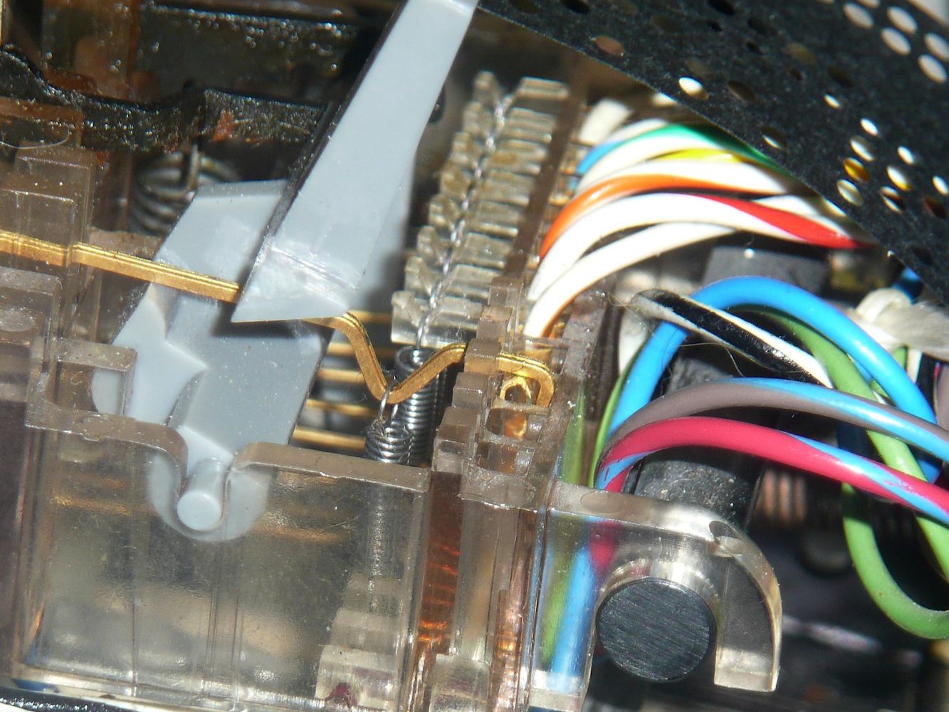
Pressing down on the contact wires with the meter probe made a connection. Close inspection of the contact wires showed that they pivot at the front of the paper-tape reader; the operating lever, the tape-out sensor and the tape-tension sensors all lift the contact wires off of rear contact when the reader is supposed to be off. The problem was in the front pivot point. Instead of making firm electrical connection with the front contact, the tail of the contact wire was hooked over the front edge of the plastic housing for the front contact. Lifting the wire and pushing it one or two millimeters forward was all it took to make it seat firmly so it pivots on the contact point. This fixed the problem. The fix is subtle enough that it is hard to see in the attached photos unless you alternate rapidly between the two images (enlarged) to see what changes (a technique astronomers refer to as using a blink comparator).
It is fair to ask, how did these contact wires get out of adjustment?
In our previous repairs to the paper-tape reader, listed under
Bug 7, we replaced the reader control
lever on
Feb. 19, 2014.
In the close-ups given here, the lever in question is the grey diagonal
piece dominating the left half of each photo; this lever cannot be replaced
without repositioning the contact wires. We must have failed to put them back
correctly.
Bug 52: On June 22, we tried and failed to adjust the Teletype platen height. There was no difficulty adjusting the right end of the platen, but everything we tried to adjust the left end made no difference, except that we managed to break the linefeed mechanism. Try as hard as we could, no amount of wedging in the platen-height pry point seemed to make any difference in the print quality.
| |
| Left end of platen | |
|---|---|
|
|
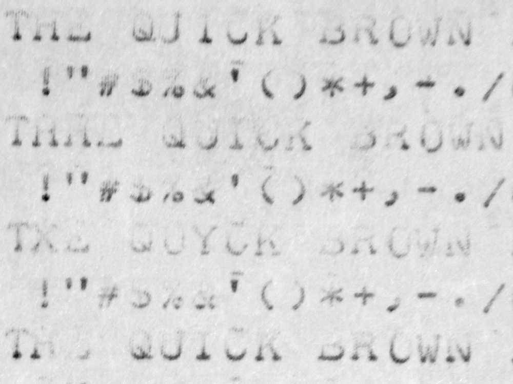
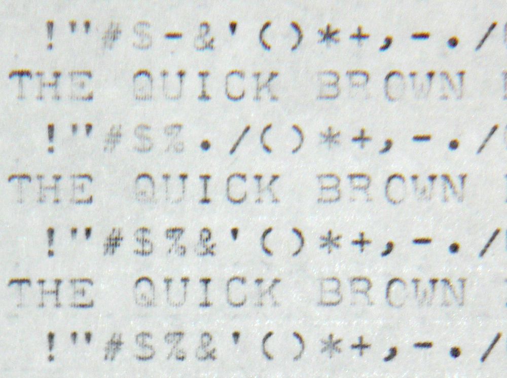
| Before | After |
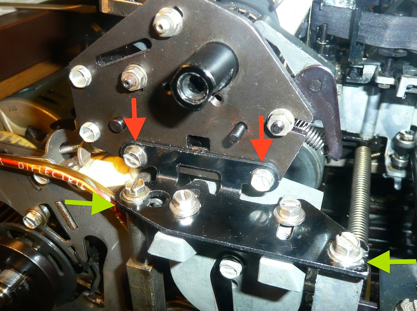
New-design teletypes have a height-adjusting pry-point on the carriage (parts 180606 and 180607 on page 9 of Section 574-122-800 of Teletype Bulletin 1184B, Parts, Model 32 and 33 Page Printer Set. The adjusting instructions on Page 109, Section 574-122-700TC of Teletype Bulletin 310B, Vol 2, Technical Manual 33 Teletypewriter Sets explains how to use this to raise and lower the typewheel, but we opted, instead, to install washers to raise the left support plate where it is screwed down to the typing unit frame. The green arrows in the photo point to the locations of these washers.
The result was a dramatic improvement in print quality, as illustrated by the
before and after print samples given here. Note in the before sample, all of
the characters are far too dark on the bottom and almost missing on top.
In contrast, the after sample shows many letters well balanced from top to
bottom, with some letters slightly too dark on top but many well balanced,
and readability greatly improved.
For some time, we have been able to load from the PDP-8 switch register into the program counter, and then increment the program counter by pressing either the examine or deposit switches, although this is precarious, as demonstrated on April 20. When we tried to go this, however, we were frustrated that there was no evidence that we could deposit data in memory. At the very least, we expected that pressing the Deposit key would transfer the contents of the switch register to the Memory Buffer register.
So, we put some time into reading schematics and manuals, and discovered that, while the Load Address function is fairly simple, the deposit function is complex, using a large part of the logic of the CPU. Specifically, when you press the Deposit key, it:
In sum, pressing the deposit key should load the switch register into the memory buffer register and clear the accumulator, but the data path is long and failures anywhere along this path will change the behavior.
Having already noticed and repaired diode failures on several R211 boards (the boards holding the program counter, memory address and memory buffer registers), we decided that it was time to blindly attack the R210 boards, the boards that hold the accumulator and a significant part of the ALU logic.
|
| Checking and replacing diodes |
|---|
| Slot number: | 06 | 07 | 08 | 09 | 10 | 11 | 12 | 13 | 14 | 15 | 16 | 17 | 18 | spare |
|---|---|---|---|---|---|---|---|---|---|---|---|---|---|---|
| Bad diode count: | 1 | 4 | 1 | 2 | 1 | 4 | 1 | 3 | 1 | |||||
| R210 boards in rows PA and PB | ||||||||||||||
Once we'd gone through all the diodes, we powered up the machine and found that all but one bit of the memory buffer register could now be loaded from the switch register. Swapping the R210 board involved with that bid did not move the problem, but when we swapped the corresponding R211 board with its neighbor, the problem bit moved.
We consider this a major breakthrough because it means we have successfully
move data through all bits of the accumulator to the memory buffer register.
This is the first time we have successfully moved any data through the
accumulator.
Given the frequency of bad diodes on the R210 boards, we decided to check all the diodes on the R211 boards. Here is what we found:
| Slot number: | 07 | 08 | 09 | 10 | 11 | 12 | 13 | 14 | 15 | 16 | 17 | 18 | |
|---|---|---|---|---|---|---|---|---|---|---|---|---|---|
| Bad diode count: | 1 | 1 | 3 | 2 | 3 | 1 | 1 | 2 | 1 | 2 | |||
| R211 boards in rows PC and PD | |||||||||||||
Bug 64: Replacing these bad diodes made no change in the behavior of the machine. We can load the memory data register from the switches by working the deposit switch, but when we try to examine what we thought we were storing in memory, we get all zero.
Given the frequency of bad diodes, we should probably go through every board
in the entire machine checking diodes. We also need to start checking to see
whether a memory cycle is actually occurring when we work the deposit switch or
the examine switch.