Introduction
This is the story of an engineering consulting job that I took with
Basic Telepresence Incorporated. For several
years in the late 1990s, they provided me with good summer support — my
academic appointment was on a 9-month basis. We developed an excellent
product, a pan-tilt-zoom camera mount called the Trippy, and we patented
it. The Trippy had, for a while, a global market and significant public
visibility, but the company folded.
I attribute the failure, in part, to misdirected effort and time
wasted developing kluges that probably delayed the release of the mature
product by about a year. As I understand the story, the company ran out
of cash at about the same time we'd made the first machines that really
did what we'd had in mind at the start.
This is also the story of what you might call a virtual company. It's not
clear to me that they ever had more than 4 employees. I never met any of
them, doing all my work by phone, e-mail and (for actual physical artifacts)
mail. The company outsourced almost everything. I was the engineering
contractor. Machining and printed circuit boards were handled by other
contractors.
Contents
Drawing copyright © 1997, Basic Telepresence Inc.,
fair use of an orphan work.
|
On June 5, 1997, I received a phone call from Larry Honig, representing a
start-up company called Basic Telepresence Inc. inquiring if I would like
to help them design a pan-tilt camera mount.
He called me because of my expertise in controlling
stepping motors.
The company name was chosen, he explained, because they wanted to get into
the teleconferencing marketplace with a way to allow remote viewers to
control the camera on the local conference table.
The people at Basic Telepresence had decided on the word Trippy to
refer to the pan-tilt camera mount they wanted to build. This name was
chosen to resonate with tripod and with the kind of virtual travel
that Basic Telepresence was intending to support. And, of course, they wanted
a name that was cute.
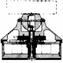
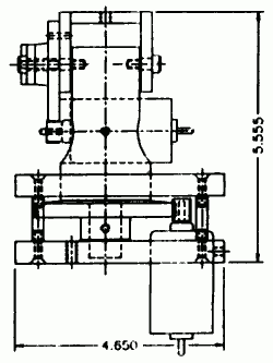
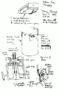
We talked, and he faxed me a CAD drawing dated May 6 of the prototype
pan-tilt mechanism he was thinking of building, along with a hand-drawn
sketch of some ideas for an enclosure for the mechanism. The CAD drawing
had the name Bill Richards on it, and as it turned out, Honig and Richards
were the entire company at that point. Bill Richards was a yacht designer
and had plenty of experience with mechanical design.
There was nothing particularly innovative looking about the initial proposal
for a mechanism. I'd seen similar mechanisms used for the cameras we used for
remote teaching, something I'd done occasionally over the previous decade. I
thought it was awkward for the following reasons:
- The pan motor hangs down below the mounting plate (although the enclosure
they proposed would have hidden this.)
- The tilt motor is on the rotating pan assembly, so the wires to that
motor will flex every time the machine pans.
- The stability of the vertical axis depends on two bearings barely an
inch apart, one of which awkwardly large.
Drawing copyright © 1997, ownership unclear, either
Basic Telepresence Inc. or Douglas W. Jones,
fair use of an orphan work.
|
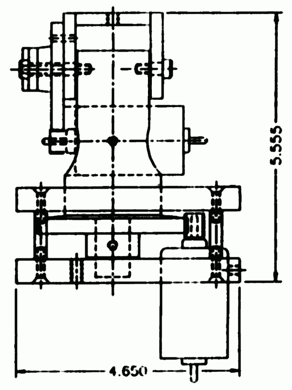
I replied the same day with a proposal for a completely different mechanism,
one that had both motors rigidly mounted in the base of the pan-tilt
unit. I was thiking in terms of 3 injection-molded plastic parts, a tilting
camera cradle, a "can" or rotate head that gives the pan motion,
and a base that holds both motors. The key part is the shaft running up
the center, with a bevel gear on top engaging a crown gear on the tilting
cradle.
I sent this drawing after I orally agreed to consult, but before I signed
any agreement, so the copyright status of the drawing is unclear.
The central idea of the invention is that, to tilt the camera, the tilt
motor turns the shaft while the pan motor holds the can in position. To
pan, both tilt and pan motors must turn in synchronization. This is quite
unlike the original proposal, where the two motors are orthogonal. I proposed
this idea because I assumed that an integral motor controller could easily
control both motors while offering the outside world control over pan and tilt
as if they were orthogonal.
The inspiration for this idea came from childhood visits to Dutch windmills
where the head of the windmill rotated around a central shaft that also served
to transmit power to the machinery below. The can is analogous to the rotating
head of the windmill, while the base is the tower and the tilting camera
platform is the spinning windmill blades.
It took a little convincing, but eventually, Bill Richards at Basic Telepresence
agreed. One key thing that convinced them to give my design a try is that it
had very few parts compared to their original proposal.
By June 10, we understood that there was a choice between a smart mechanism
with an on-board processor to convert commands in terms of absolute pan and
tilt angles into stepping motor control, and a dumb mechanism where an external
host computer was responsible for direct control of the stepping motors.
Very early, we realized that we'd have to build the dumb design to learn how
to write code for the smart design, and we narrowed the choice of processor
down to the Intel 8051 or something from the Microchip PIC family.
By June 12, we knew we'd be using small "can stack" stepping motors with
7.5° per half step, probably from HSI and probably with bipolar windings
requiring one dual H-bridge per motor. I began designing parallel port
interface boards around this, with a third IC to generate 1 ms timing pulses
so that standard printer drivers for the IBM PC parallel port could run the
board at 1000 steps per second.
Drawing copyright © 1997, Basic Telepresence Inc.,
fair use of an orphan work.
|
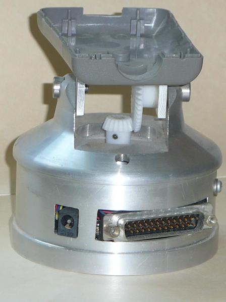
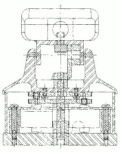
The drawing shown here, from July 1 has no provisions for a circuit
board. We agreed that the first priority was to build a dumb circuit board.
that is, one with no on-board computing power. We therefore christened our
prototype as the Dumb Trippy.
The key question surrounding the circuit board was how much circuit board is
required, so my time was being spent on circuit board layout issues, trying
to pack components into the available volume.
My June sketch had suggested a vertical circuit card on the opposite side of
the center-post from the motors, but the motors we'd settled on were
"can stack" permanent-magnet stepping motors. Those are wider than they
are tall. The motors forced the dimensions of the base, and that created
horizontal space for a circuit card. We opted to mount that card on the
base, with a cutout in the side of the base for the plug.
On the side, we were still tossing speculation back and forth about the
command vocabulary for the Smart Trippy. Because the company was called
Basic Telepresence, we called this the BT command set and decided early that
commands would be textual, encoded in ASCII (a UTF8 subset), and that
each command would begin BT. Another early decision was that we would
think in terms of having multiple Trippys listening to a single command
stream, so each Trippy would have a number and BT commands would begin
BTn, where n is the number or name of the Trippy to which
the command is addressed. This suggested things like BT4x=-12 to
mean that Trippy number 4 should set x (the pan angle) to -12.
We were still wondering whether numbers should be decimal or some other
representation and whether an equals sign would mean "set this variable."
On July 7, Basic Telepresence Inc. registered the word TRIPPY
as a trademark.
I'd previously built stepping motor controllers you could directly run from
an IBM PC parallel port, so I set to work designing such an interface for the
Dumb Trippy. It takes 4 bits to control one stepping motor, the PC
parallel port is 8 bits wide, and the Trippy has 2 motors, so the design was
pretty trivial, sending 4 bits to the H-bridge chip for each motor.
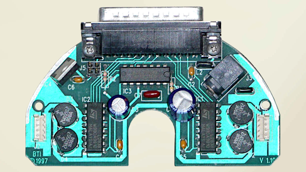
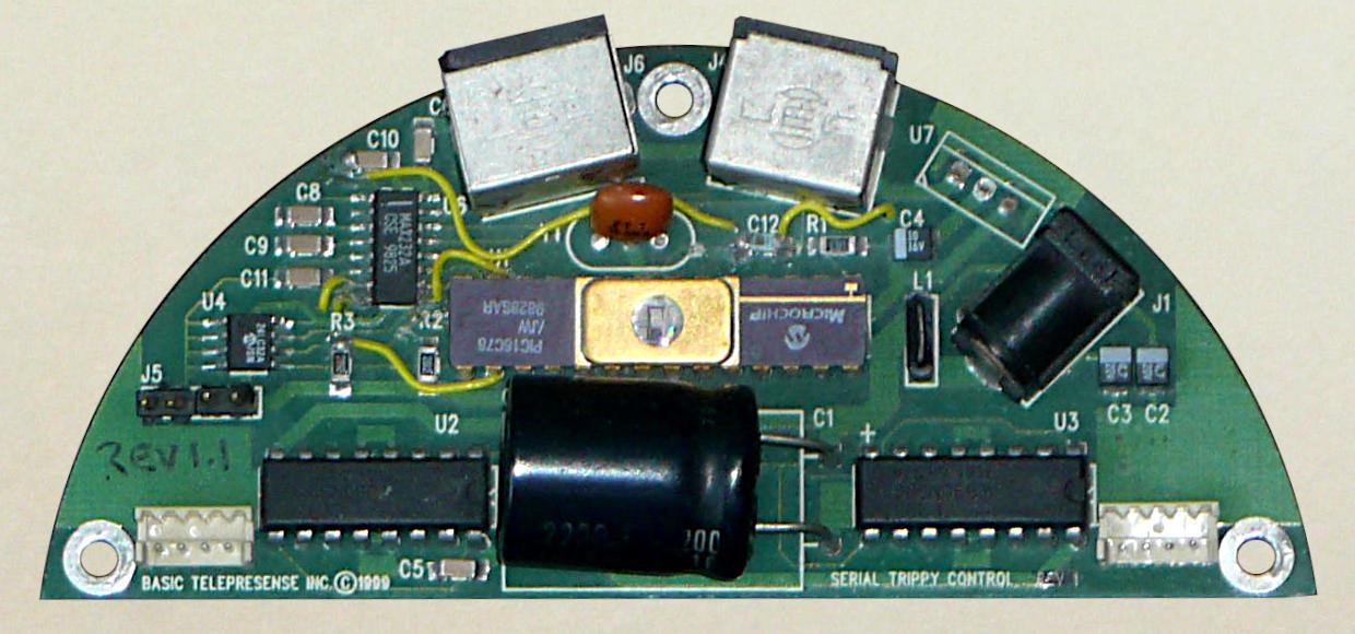
The white sockets on the far left and right of the board are for the wires
from the motors. The circular components next to the plugs are diode bridges
used to protect the control circuitry from switching surges. The integrated
circuits IC1 and IC2 just inboard of the diodes are L293B dual H-bridges;
these take TTL voltage levels from the parallel port and convert them to
12-volt power for the motor windings. The voltage regulator on the upper
left and the smaller electrolytic capacitor provide logic power to the chips.
IC3, the upper IC by the parallel port socket, is a 74LS122 retriggerable
monostable multivibrator. It takes the downgoing edge of the strobe output
from the parallel port and delivers this to the acknowledge and busy inputs
of the parallel port with a delay that can be used by software on the PC
driving the Trippy motors for timing. Our prototype included parts that
set the effective parallel port speed to 1000 command bytes per second.
There's a little 4-pin header on the left side of the parallel port plug, J5.
This was added to support speculation that the Trippy might need some
status LEDs. In addition to the 8 data bits on the parallel port, there are
some bits that don't really take part in the high-speed parallel data transfer.
Initially, just one of these was brought out, AUTOFD
(pin 14 on the parallel port), along with power and ground. Later we brought
out SLCTIN, (pin 17 on the DB25 version of the parallel port).
I delivered a preliminary board design to Basic Telepresence on July 16 and
a revised design on August 5. A subcontractor delivered printed-circuit
artwork on August 18, with errors (some of mine, some of theirs).
The demise of the parallel port in more recent personal computers significantly
complicates the design of products like the Trippy today by preventing the
use of simple-minded stopgap designs like this. This is a great pity, although
the rise of the Raspberry Pi and the Arduino largely fill this gap for modern
developers.
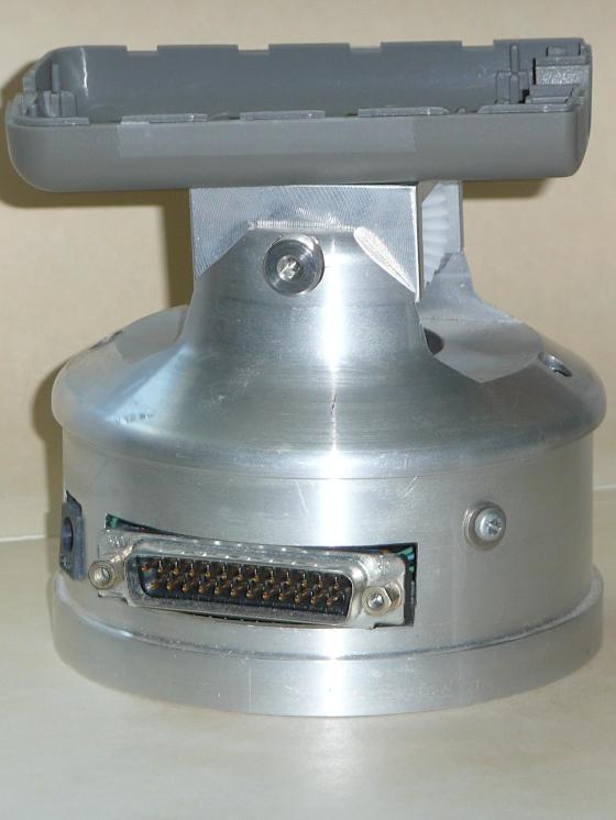
Basic Telepresence had two prototypes made to test our design, and I got one
in the mail just before Sept 5, about 3 months after I'd started consulting
with Basic Telepresence. By that time, I was spending more time thinking about
the Smart Trippy. Among other decisions, Bill Richards hit on
the idea of a ball-shaped tilt head. That stroke of genius allowed the
tilt gear to be completely hidden except when the ball was at the extreme
of its tilt range. This turned out to be important to getting UL certified
since it eliminated a pinch hazard.
I immediately wrote a crappy little bit Qbasic code to control the Trippy,
merely spinning both motors constantly day in and day out. I sent the code
to Basic Telepresence on Sept. 8, and immediately left it spinning my
prototype for the next 24 hours so I could measure the power consumption and
how hot the thing got under constant stepping.
In retrospect, I regret sending that code off, because it didn't use any
parallel port printer driver, but just used IN and
OUT commands to directly tinker with the parallel port hardware;
that was entirely legal to do under MS-DOS. My code didn't use interrupts,
it just used polling to see if the little timer in the Trippy had declared
a millisecond to have passed since the last strobe.
There's nothing wrong with this for a quick and dirty test,
but as far as I know, Basic Telepresence was still using code derived from
my crappy foundation into 1999 (although they seem to have translated it to C).
I was already developing a much nicer C-based foundation that ran assuming
output to the parallel port via a standard printer driver. This code worked
just fine under various versions of Unix where user code had no direct access
to the parallel port hardware, but the folks running Basic Telepresence weren't
really software people. It was only in February that I heard that my C code
was seeing any use.
With our prototypes in hand, we began to realize its faults.
The step size of the motor was too close to the gear tooth size of the pinion
on the motor, and that meant that the natural resonance of the motor after
each step was converted to noise and a tendancy to jam the gears if there
was any play. The way we were centering the pan gear on the Trippy lid led to
it being slightly eccentric, leading to excessive play at some pan angles, and
there was too much play in the bevel gears on the tilt axis. Finally, the
lid tended to wobble a bit on the support shaft. Either it needed a longer
bearing or it needed edge support on the can.
Drawing from U.S. Patent 6,027,257, therefore in the public domain.
|
The next size larger motor from HSI was sill 7.5° per half step, so to get
both more torque and a smaller step, we agreed to add a small gear tower by
each motor. By Oct. 1, this had led us to enlarge the base to a 4 inch
inside diameter. This led to a redo on the parallel trippy board with no real
change to its logic or function, and aside from questions of effective step
angle, it meant that all of the software we had written for the Dumb Trippy
would still work.
By Nov 5, the Dumb Trippy design was finalized, ready to send out the circuit
board design to one subcontractor and the case design to another. The initial
production run was short. The folks at Basic Telepresence made some
important contributions to the case deisgn, working things so that all parts
could be manufactured from bar stock on a CNC turning center. I had always
thought in terms of injection molding, but CNC turning is fast and cheap
enough to be competitive for production runs into the hundreds. CNC machining
of aluminum also allows for a very nice anodized finish.
Basic Telepresence went to Comdex, a big electronics trade show in Las Vegas,
at the end of 1997 to launch the newly re-engineered Trippy into the market.
I gave a talk to the U of Iowa Electrical and Computer Engineering Professional Seminar on November 20 entitled From Concept to Comdex, the Story of the
Trippy.
The Basic Telepresence Booth at Comdex just barely managed to get their demo
working, using an old circuit board from the prototype dumb Trippy hacked to
fit the new larger base. That Trippy ran continuously at Comdex, panning back
and forth 90 degrees and tilting up and down 20 degrees.
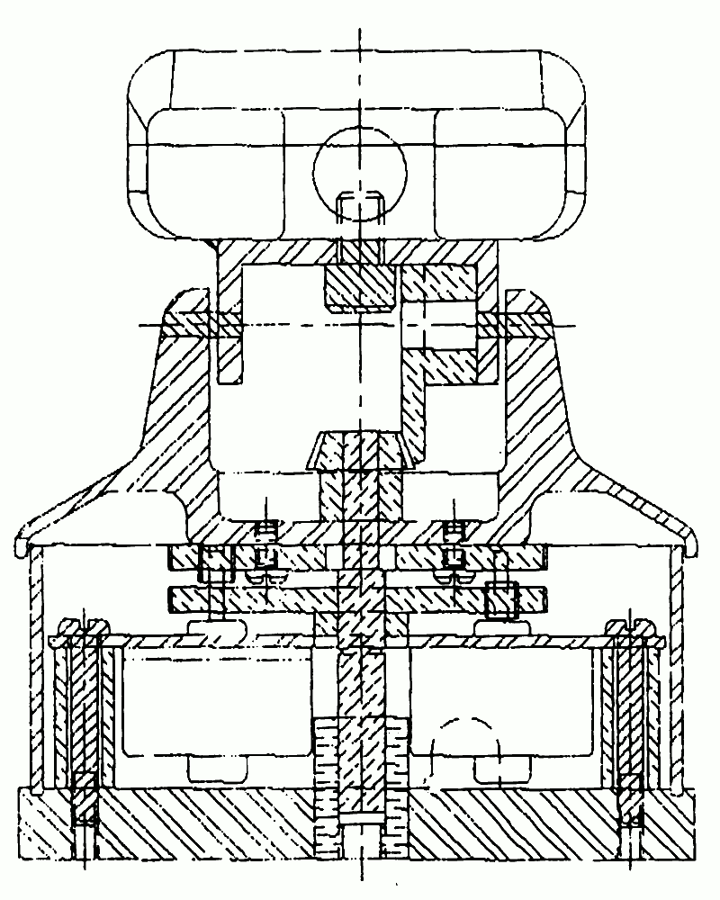
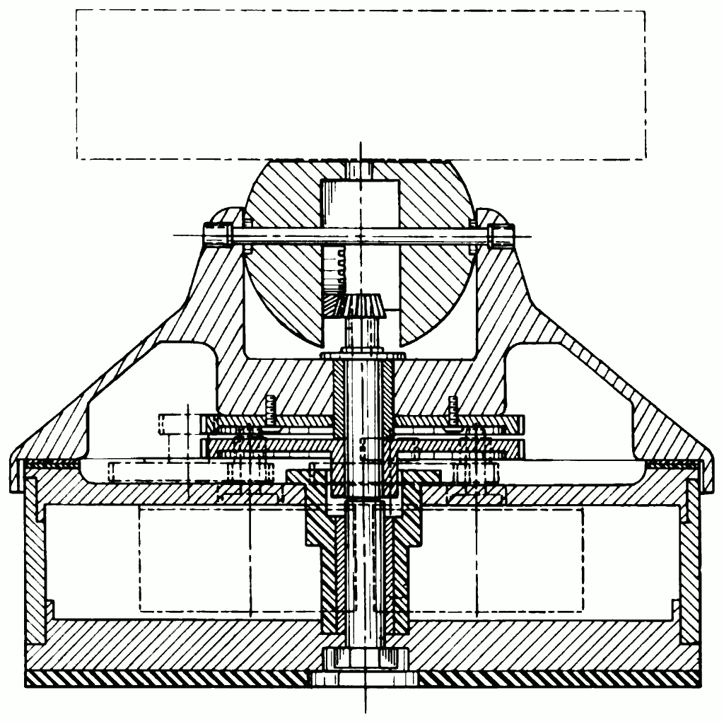
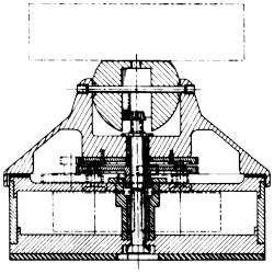
The folks at Basic Telepresence prepared a patent application based
approximately on the Dumb Trippy as it was at the end of 1997. Preparing a
patent is a messy process, so the application was not formally filed until
March 26, 1998. The cross-section drawing here is from that patent
application.
The drawing differs in a few ways from the production Dumb Trippy: It does
not show any provision for mounting the circuit board. We machined a well into
the base to accomodate that. The drawing also shows the wall of the can as
a separate piece of tubing, while in our production model, it was integrated
with the motor support plate. The gear towers are only ghosted in in the
drawing.
If you compare the patent drawing with the similar cross section of the
original prototype, you'll see that the whole assembly is squatter looking
and broader at the base. It incorporates the ball-shaped tilt head and the
teflon bearings supporting the rim of the lid that the folks
at Basic Telepresence came up with in September, while setting the tilt
pinion in a well in the lid so the ears ears supporting the tilt axis are
very short was my suggestion.
I didn't see the patent application before they filed it.
I knew they were applying, but I didn't see it until
U.S. Patent 6,027,257
was granted in early 2000. Had I seen it, I'd have noticed that the very
first claim in the patent, the one on which all the others rest, was what
I'd invented and given them in my June 5, 1997 sketch. Clearly, my name
should have been on that patent, and in a sense, omitting my name may make
the patent technically invalid (although since it's now an expired patent, it
hardly matters).
The trip to Comdex and other marketing adventures led to a digression.
I wanted to get right into the job of building the Smart Trippy control
board, but potential customers were insisting on a way to control the Zoom
settings of legacy cameras. It doesn't help that there was no industry
standard for how such zoom settings are controlled.
On Jan. 5, 1998, I was asked how to use the 2 auxiliary pins I'd put on
the Dumb Trippy control board to control the zoom function of a camera.
I had to provide sample Qbasic code for how to control the auxiliary
outputs, and I gave Basic Telepresence a simple circuit for an auxiliary
board to decode these 2 bits of data to work the push buttons found
on some cameras to control their zoom function.
On Jan. 13, the topic changed to an alternative to the use of bevel gears
to operate the tilt axis. The basic idea was to cut a screw thread on
the top of the center shaft so that turning the center shaft would raise
and lower a nut on that shaft to drive the tilt platform. This made it into
the patent but I don't know if it went into production.
By Jan. 22, I was getting frustrated, "My guess is that we're only weeks
away from a perfectly good product that could meet the original design
specs and sell a few thousand, and yet we seem to be delaying production
indefinitely by trying to push our half-designed product to meet the needs
of a market that poses far more rigorous demands! ... my basic advice
remains ... Get to market, get a product, be conservative about what you
promise it will do in terms of load and carrying capacity, and then worry
about things like a high load capacity version, a smart version, and a
version that can tweek the controls of a commodity camcorder."
By late Jauary, Basic Telepresence had a camera on a tower in Watertown
Mass, and another camera at the San Francisco Giants ballpark, both
of which could be controlled by visitors to the Basic Telepresence web site.
Questions about alternative ways to drive the tilt axis and ideas for
controlling zoom on existing cameras continued to fill my available
time until February 10, when I received e-mail that ended "we ought to do
the smart Trippy board soon! This is a colossal waste of time!"
A dumb Trippy was finally sold for cash on March 19, 1998 for $1428.50,
and 4 more in the week following. My records show that I put in no
significant work on the Smart Trippy through the summer, while I continued to
answer numerous questions about gear ratios, tilt mechanisms and power
requirements.
The Boston Marathon, held on April 20, 1998, was a big day for Basic
Telepresence because they had set up at least one Trippy along the route
giving anyone on the internet the ability to direct the camera. This gave
them a serious publicity boost.
By December 6, 1998, Basic Telepresence had a web site,
basict.com.
The site featured on-line control of webcams at Watertown and Harvard Square
Massachussetts, along with two views of Pacific Bell Park in San Francisco,
as well as 11 other cameras on Trippy platforms. I gather that these webcams
attracted enough attention that Basic Telepresence was actually making useful
money by selling advertising on their camera web sites.
Drawing copyright © 1999, Basic Telepresence Inc.,
fair use of an orphan work.
|
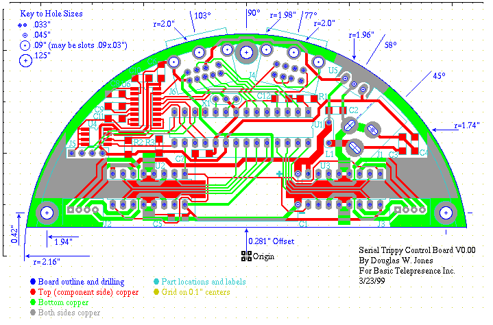
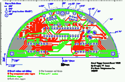
It was not until March 1999 that I began serious work on the Smart Trippy.
The version shown here, dated March 23, was verey preliminary and contained
a number of errors. The important point of this design was to figure out
what pins of the microcontroller would connect to what peripherals. Those
desisions were driven by board geometry and needed to be made before I could
start programming.
This was my first serious venture in surface-mount design,
Note U4 and U6 on the upper left are surface mounted as well as a number of the
smaller capacitors and resistors. Other chips are through-hole mounted, and
this actually mattered for the microcontroller because it is wired for
in-circuit programming. The connections for this would conventionally be
made using a jack of some kind, but I opted to use a DIP-clip for programming.
This decision required that the microcontroller be through-hole dual-inline
package (DIP).
The smart part of the Smart Trippy was a PIC16C73 microcontroller, U1 on the
circuit board, clocked at 16MHz. This little computer packed an 8-bit CPU,
368 bytes of RAM and 4K 14-bit words of EPROM on one chip — it was a
Harvard Architecture machine, so there was no need for instructions to have a
format that related to the RAM byte size.
On-chip peripherals included 3 real-time clocks and a USART for a serial data line.
The I/O pins on the chip were all programmable, so they could all be used
for parallel input/output if they were not committed to special purposes such
as USART support.
4 bits of parallel output go from the PIC to control each stepping motor.
The motor drivers, U2 and U3, are L293D dual-H-bridge chips, with integral
protection diodes. U4 is a 24C32A flash EEPROM chip connected to the PIC
by an I2C 2-wire serial data bus. We added this to serve as
something of a "file system" for the PIC, so it could remember configuration
information from one use to the next.
The board has 2 mini-DIN plugs. J4 is the serial port wired to be compatable
with Apple MAC SE serial cables, while J6 is basically a 6-pin serial port
intended to control the zoom features of some kind of camera, but with no
committed purpose in the board design. Similarly, J5, a 4-pin header on the
left side of the board, is a 2-pin parallel port intended to control LEDs or
similar items inside the Trippy.
A pair of prototype boards was sent to me on May 5.
I started work on the code for the smart trippy on June 1, 1999, although
the architecture of the code was something I had in mind from the start. The
architecture was basically the same as the architecture I'd settled on for
a Braille printer I'd built in 1980:
- Bottom layer: Interrupt dispatching and return
- Middle layer: I/O drivers
- Top layer: The application
The PIC architecture has as an
advertised "feature," an 8-level built-in hardware stack. Feature is not the
right word, because this means that you can only safely nest calls and
interrupts to 8 levels. I opted to live within the rule that only 4 levels
of nesting could be used by an interrupt service routine and only 4 levels
could be used in application code. The initial code came nowhere near
to pushing these limits.
The driver layer includes startup code to initialize
all of the chip configuration registers, for example, setting which I/O
pins are generic paralle port pins and which are committed to specialized
on-chip devices. This naturally includes initializing all the devices to
their default states.
The primary real-time clock ran at a fixed 5kHz rate.
It was in charge of all motor motion, checking at each interrupt if it
was time to take a step with either motor and taking those steps. This was
not trivial, since the control model used an acceleration table to determine
the time between steps as a function of current speed and the number of steps
until the destination.
When neither motor was in motion, the primary and secondary real-time clocks
cooperted to reduce the power consumption of the motors using a 5kHz pulse-width
modulation scheme.
The big trick in the Smart Trippy was to get pan and tilt (X and Y) motion
when the two motors are not orthognal. To do this, pan steps always turn
both motors, while tilt steps turn just the tilt motor. This worked very well,
even allowing diagonal moves without doing any fancy computing.
There was also a driver for the asynchronous serial port; this was very
conventional, with a pair of FIFO queues, one for input, one for output.
Sitting above the I/O drivers was the application. This operated by waiting
for input from the outside world and then decoding that input and sending
any requested replies. The camera control protocol was called the
BT protocol because, as already mentioned, Basic Telepresence was
the customer and because every BT command began with the two letter ASCII
string BT. The protocol allowed the remote user to set or inspect
any of the 16-bit motor control variables, by name.
The key motor control variables were X, Y and Z,
the target pan, tilt and zoom values to which the camera was to be set.
Other variables included I and J, the current pan and
tilt values as well as essentially all the working variables involved in
motor control including the acceleration table.
In our final design, the command "BTX50=" would set the variable
X to 50, initiating a pan move if 50 was not the current pan
coordinate, and "BTI?" would inquire about the current pan
coordinate.
The initial version of the code did nothing to support zoom and did not
include code to use the Flash EEPROM chip, nor did it include code to
help the Trippy find the home position. These ommissions were deliberate.
The initial version did, however, include 16 bit decimal input output,
because the BT protocol required it.
Developing
these
was not easy on the PIC because the processor had no support for 16 bit
arithmetic or multiplication and division.
The initial version of the code took 2 months to write and test. I sent a
non-working draft of the code to Basic Telepresence on June 16, basically as
an off-site backup. By June 21, I had a Trippy in hand to try to control
with the new board. By June 23, I had the pulse-width modulation scheme
working to reduce power consumption by an idle Trippy. The code was basically
all written by June 30, along with a software specification and a hardware
manual. By July 29, everything was basically working.
By August 10, 1999, it was clear that programmers working on a PCs running DOS
needed some kind of flow control on the return channel. The I/O drivers under
DOS didn't listen to the asynch port except when the application was waiting.
Fortunately, the DOS drivers did support RTS/CTS handshaking for asynch input,
so we decided to support that using
RS-232 lines on the serial port that we'd previously left unconnected.
Squeezing the new wires in was an interesting exercise. Fortunately, the
RS232 level converter chip we used had two spare channels, but we ended up
changing some of the pin assignments on the PIC to simplify wire routing.
That meant some additional small software changes. In addition to doing new
printed circuit board artwork, I also reworked all three of the boards I had
so that they'd conform to the new design. The photo shows one of the
reworked boards.
The new firmware for the reworked boards was delivered on Sept. 7, 1999, but
not entirely debugged. Of course, I also updated all of the documentation
and included an exercise program that would keep a Trippy very busy pointing
in random directions indefinitely.
By Sept 22, the Trippy positioning code worked correctly. I sent that code,
and I sent the instructions for reworking the boards Basic Telepresence
had on hand, along with one of my reworked boards as an example.
Of course, the reworked board I sent east on Oct. 5 was also loaded with the
current firmware.
It was fun to strap a felt-tip pen to the top of the Trippy and then gently
hold a pad of paper to it as it scribbled under the control of my exercise
program. We still weren't using the Flash memory, nor was there any zoom support.
In early 2000, I made my first effort to support the Zoom function. The
folks at Basic Telepresence had sent me an off-the-shelf Canon WL-61
camcorder that had an infrared remote to control the camera. I got a
scope and an IR photodiode and began to study the signals output by the IR
remote. We quickly determined that the IR signal used a 40kHz carrier,
with bits sent in serial form, 22 carrier cycles per bit, and
128 bits (8 x 16-bit words) per command. Instead of trying to decypher these
commands we simply decided to ape them without understanding.
So, I added code to the Trippy to accomodate 3 16-bit zoom commands in
memory beyond the acceleration table, set aside an additional variable
used to set the carrier frequency, and added code to send the IR start
code on initialization and the IR zoom in and zoom out codes, as needed,
in response to BT commands. The only hardware required was a plug in the
zoom jack connected to an IR LED that could be pasted over the camera's IR
port. I delivered code supporting this zoom model on Feb. 9, 2000.
I also worked out how to control the zoom function on a JVC RM-V705B
camera. This was also used a 40kHz IR carrier, with shorter packets
but otherwise similar, so we could use the same Trippy code with different
values loaded in the command strings.
In retrospect, while this was an interesting interlude, it didn't lead
to a valuable product and it, combined with earlier work on ill-conceived
zoom functions done for the dumb trippy were responsible for yet more
delay in developing the mature version of the Trippy and thus indirectly
responsible for the eventual demise of Basic Telepresence.
The Mar. 4, 2000
basict.com
web site was featuring cameras at the Smithsonian, the National Zoo, and
several overseas sites using dumb Trippy platforms with zoom mechanisms,
although I was not really in the loop as to how they were working the zoom.
The company seemed to be prospering, although the sales were not focused on
in the domain we'd originally imagined. Most cameras were being sold mounted
upside down in domes that could be hung on light poles or on the outsides of
buildings, and the biggest market was industrial monitoring and security.
On Feb. 16, we began to seriously investigate position sensing. Up to that
point, we'd been initializing the Trippy by driving the pan axis at low
speed against the left stop, then driving the tilt axis down, still at low
speed. Once we knew the Trippy was jammed in a known position, we set the
speed limit up to the maximum and sent it to home. This worked, but it was
slow, and during use, if for some reason, the Trippy skipped steps, it would
slowly lose track of where it was.
What we hit on was to have reflectors on the tilt gear and on the inside of
the lid, with upward looking sensors watching them from below. The Trippy
controller could monitor these to see if it was left or right of center,
and when centered on the pan axis, whether it was looking above or below
center. Furthermore, when either sensor saw a transition from 1 to 0, it could
reset the associated counter, so the Trippy would automatically and fairly
regularly recalibrate its tilt and pan position during use and so it was easy
to make a very quick recalibrate move at startup.
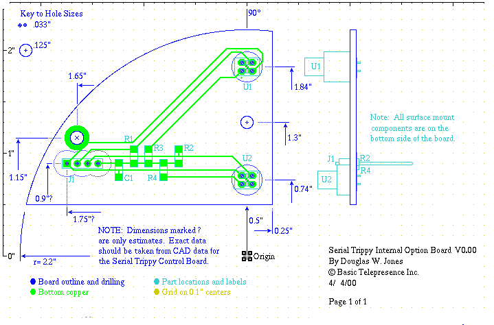
To make this work, I had to design a simple daughter board
that mounted on the underside of the motor mount plate and plugged into the
internal option jack we had long provided. The photo here shows the
underside of the lid with stainless steel reflectors installed. The drawing
shows the design of the printed circuit board that looked up through holes in
the motor mount plate at the reflectors.
The photosensors looking up at the reflectors on the inside of the Trippy lid
were nice little units that had, in one housing, an infra red LED and a matching
phototransistor. The only other circuitry required were 4 resistors, 2
pullups for the inputs to the PIC and 2 current limiters for the LEDs. All the
through-hole parts were over holes drilled in the motor mounting plate, so the
entire board was screwed down tightly to the bottom of the plate with just the
sensors pointing up at the underside of the lid.
By June, I had a prototype in hand and could begin debugging the tilt and
pan feedback code. While waiting for that prototype, a student and I
got the Flash EEPROM working, complete with changes to the BT protocol
to allow the Trippy control variables to be saved and restored in flash memory.
By the end of June, I had two working Trippys with feedback and with
state memory that automatically loaded from Flash EEPROM on power up so the
Trippy could automatically home on a preset location from state memory.
I sent one back to Basic Telepresence along with code and manuals.
The folks at Basic Telepresence weren't happy with the camcorders we'd been
playing with, and they discovered that Sony sold a "camera brick" or
"camera block module"
that was, essentially the guts of a high-end camcorder without the "corder"
half or any packaging, that is, just a naked video camera plus a
zoom lens. I recall
that it had something like a 20 to 1 zoom range, which is very very good.
By May 17, I had the "block cam" documentation in hand, and a month later,
I had a camera. The camera had a strange serial data protocol, obviously
designed by someone with no real connection to the conventions of serial data
transmission (they sent the most significant bit of each 8-bit packet first).
Also, it used RS-232 levels, and our auxiliary connector on the Trippy had
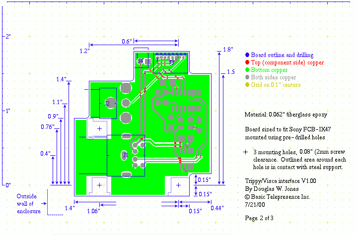
only TTL levels. So, in addition to designing a housing for the camera, we
had to stuff a little board in with the camera to take TTL levels from the
Trippy and convert them to RS-232 levels. We called this board the wedge.
The need for this board was finally clarified by Sony in mid July.
So I designed a little board to fit the back of this camera and sent it to
Basic Telepresence on July 21. By mid August, the code for asynchronous
output to the accessory port was working. Unlike the primary asynch port
on the Trippy, this was done all in software on pins controlled as a simple
parallel port, so it wasn't trivial. I got the Sony camera working on Aug. 24,
and the next day, I sent Basic Telepresence a stack of boards pre-loaded with
firmware to support the Sony camera along with the code.
I learned of a bit of a management shakeup on Sept. 13, when the previous
company president Larry Honig told me that he'd retired and that the former
chief engineer Bill Richards had taken over. As it was never more than a
4-person company, as far as I could tell, this was a bigger event than I
understood.
I also hadn't known that, on June 16, 2000, there was an corporate
reorganization, with the dissolution of the Massachussetts corporation
and the formation of a Deleware corporation. It still isn't clear to me
whether these two events are coupled nor is it clear to me exactly when
Larry retired.
On Sept. 26, I noted that Basic Telepresence really needed to amend the patent
to add my name as a co-inventor. My contribution to the design was
arguably a "work for hire," arguably, because it was made on the first day
of my work with Basic Telepresence before we'd formalized any agreement.
Thus, putting my name on the patent was not so much a matter of ownership
as it was a matter of protecting the patent by correctly
naming all the inventors.
I can't find the exact date of the end of Basic Telepresence, but I recall
getting a notice saying that creditors should file their
claims with the court. Basic Telepresence owed me a few thousand dollars,
but I figured that was likely to be small change so I ignored the notice.
In retrospect, I should probably have responded to that notice and asked
either for the patent or for the copyright on the code I'd written that
Basic Telepresence never paid for.
The old web site at
basict.com
still existed on December 6, 2001, but by March 2001, it had been completely
redesigned and referred to a new Internet domain at the bottom of the page,
btivideo.com. The last archived copy of the web site is from
July 27, 2002.
Searching through the Internet Archive, it's not
hard to find archived copies of the
btivideo.com
web site between 2001 and 2006.
It is evident that the redesigned content on basict.com after March
2001 was a redirect to btivideo.com.
The web presence under the new regime very static, little obvious
change between 2001 and 2006; the corporate history on those archived web pages
notes that "In December, 2000, BTI entered into a strategic alliance with
PicoStar, LLC, a technology investment company," which I gather really means
that PicoStar bought what was left of Basic Telepresence.
On November 29, 2004,
U.S. Patent 6,027,257
was assigned to the PTZ Liquidating trust and then to Micronets, LLC.
This, presumably, marks the final end of the company.
The archived copies of the BTIvideo web site do contain a nice list of
customers, with brief descriptions of a number of Trippy applications.
Given the static nature of the web site, this was probably based on customers
as of the end of 2000. They range from
"zoo cams" and cameras at resorts and sports
venues to monitoring of hazardous machinery and construction sites.
I still think the Trippy was an excellent little pan-tilt camera mount, and
with the Sony "block cam," an excellent PTZ camera. That "block cam," by the
way, remains in production 20 years later. If I were to start over, though,
while I'd be happy to use the same mechanism, I'd build the controller as a
shield-board on top of something like a Raspberry PI. The BT protocol might
still exist, but it would be used only to communicate between the Raspberry PI
and the shield.