Trippy PTZ WebcamControl board external specification, V 1.10
Part of
the Trippy web pages
Copyright © 1999, Basic Telepresence Inc., revised and corrected, 2022, Douglas W. Jones. |
Trippy PTZ WebcamControl board external specification, V 1.10
Part of
the Trippy web pages
Copyright © 1999, Basic Telepresence Inc., revised and corrected, 2022, Douglas W. Jones. |
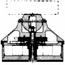
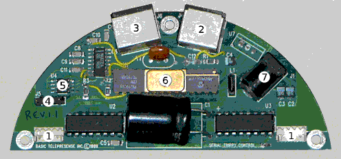
The Serial Trippy control board is a D-shaped board that fits in a circular space 2.16 in. in diameter, with a straight edge that comes 0.281 in. shy of the center. The outer edge of the board is designed to rest on a 0.1 inch wide ledge, with which it should be in thermal contact to provide cooling for the on-board components.
|
The Serial Trippy control board, V 1.10, provides the following functions:
Each motor plugs into a 4-pin 2-mm header mounted on the control board. Pins are numbered left to right when the board is viewed from the component side, curved edge up.
| 1 | 2 | 3 | 4 |
|---|
| 1 | + | – winding 1 |
|---|---|---|
| 2 | – | |
| 3 | + | – winding 2 |
| 4 | – |
The RS-232 cable plugs into an 8-pin Mini DIN connector on the edge of the board, positioned so it may be accessed through an opening in the shell of the Trippy. Standard RS-232 line voltages are supported, and the pinout of the connector follows the industry standard supported by Apple and Sun Microsystems serial ports, allowing use of industry standard interface cables. EIA flow control is supported compatably with Sun Microsystems RS-232 ports. Pin layout is shown from the connector face.
| 8 7 6 |
|---|
| 5 4 3 |
| 2 1 |
| 1 | DTR | — +10V | (output) |
|---|---|---|---|
| 2 | CTS | — clear to send | (input) |
| 3 | TxD | — transmit data | (output) |
| 4 | Gnd | — signal ground | |
| 5 | RxD | — receive data | (input) |
| 6 | RTS | — request to send | (output) |
| 7 | – | ||
| 8 | – |
External options may be connected to a 9-pin Mini DIN connector on the edge of the board, positioned so it may be accessed through an opening in the shell of the Trippy. This connector provides +5V, +12V, ground, and 6 data lines. These data lines are uncommitted. Each may be used for high-impedance TTL input or for TTL output.
Because of their high impedance, if used as inputs, the data pins must be driven by bipolar chips or auxilary pull-up resistors must be supplied. When used as outputs, 5 of the 6 data lines have bipolar drivers, one has an "open-collector" driver requiring a pull-up resistor.
See the notes on power supply for the power available to external options. Pin layout is shown from the connector face
| 9 8 7 |
|---|
| 6 5 4 3 |
| 2 1 |
| 1 | data |
|---|---|
| 2 | +12V unregulated |
| 3 | +5V regulated |
| 4 | data |
| 5 | data |
| 6 | data |
| 7 | ground |
| 8 | data |
| 9 | data |
Internal options may be connected to a 4-pin 0.1" header on the board. +5, ground and 2 data lines are available. These data lines are uncommitted. Each may be used for high-impedance TTL input or for TTL output.
See the notes on power supply for the power available to internal options. Pins are numbered left to right when the board is viewed from the component side, curved edge up.
| 1 | 2 | 3 | 4 |
|---|
| 1 | ground |
|---|---|
| 2 | data |
| 3 | data |
| 4 | +5V regulated |
A small EEPROM (Electrically Erasable Programmable Read-Only Memory) is included on the control board for storage of personality information. This has a capacity of 1K bytes.
A Microchip PIC16C76 is included on the control board. This has 8K by 12 bits of on-chip program ROM and 368 bytes of data RAM, as well as interfaces to control all of the above elements. Software for the microcontroller may be loaded into the microcontroller using a special programming fixture and a standard PIC programmer, available from Microchip and several competitors.
The board includes filter capacitors and a voltage regulator. Given a 12V unregulated external power supply (a "wall wart"), these components provide a filtered +5 supply for internal logic and external options, along with an unfiltered +12 supply for motors.
With all motors idle and no connected options, the control board will dissapate under 4.5 Watts and draw under 375mA. A total of 1.6 amps (19 Watts) may be consumed by all internal and external loads, including motors and logic. At this current, the +5V regulated supply will remain stable, but the ripple on the +12 supply will have an amplitude of up to 6 volts.
The total available logic power depends on how the control board is mounted. If no special provisions are made for cooling, the 5-volt power supply can supply a maximum of 400mA, of which 375mA may be consumed by the control board itself. Therefore, only 25mA is available for internal and external options. If the heat-sink tab on the on-board power regulator is in thermal contact with the metal base of the Trippy, an additional 100mA is available for internal and external options.
The total power consumption of the Trippy under normal operating conditions depends on both the motors being controlled and the software loaded on the control board's internal microcontroller.
If an external filtered power supply is used, the total power consumption may be increased to 2.5 amps (30 Watts). Under no circumstances should motors drawing more than 600mA per motor winding be used! This translates to a maximum motor power level of 14 Watts per motor.
The bulk of the above text is from my files. The original was a plain text document (.txt format), so in tranferring it to the web, I converted to HTML and took the time to correct various errors, add an illustration, and bring the documentation of the different connectors up to comparable standards.
Note that Rev 1.11 was the final board revision, so the documentation here does not fully cover version used in the Trippy as it went to market.
I actually used this specification as an aid in testing the firmware, particularly when I had to build cables to connect to it, but its primary value was so that the people at Basic Telepresence would have some understanding of what they were getting. Therefore the specification was revised for each board revision and delivered to Basic Telepresence.