| C = | c4 | c3 | c2 | c1 | 1 | |
| + | A = | a3 | a2 | a1 | a0 | |
|---|---|---|---|---|---|---|
| S = | s3 | s2 | s1 | s0 |
Fast Ternary Addition
Part of
http://homepage.cs.uiowa.edu/~dwjones/ternary/
Posted to the web, April 1, 2012; revised, June 27, 2013 to include unsigned carry-lookahead adders and March 12, 2015 to combine propagate and generate as a single ternary value. |
Unsigned and 3's-complement ternary arithmetic uses the values 0, 1, and 2 for each digit, while in balanced ternary uses –1, 0 and +1. Balanced ternary is equivalent to biased unsigned ternary, with a bias of half the range. The implementations of ternary arithmetic are presented here, follow the conventional sequence used in presenting binary arithmetic, working up from a half adder to a full adder, and from there to an ALU and carry-lookahead logic. Carry-lookahead logic for balanced ternary is significantly more complex than for unsigned ternary; as with other number bases, an unsigned ternary adder also computes a three's complement sum.
Ternary numbers use base 3, as distinct from the binary (base 2) numbers usually associated with digital computers or the decimal (base 10) numbers of everyday arithmetic. A single digit in number base b carries log2b bits of information. Thus, each ternary digit or trit carries about 1.58 bits, as compared to 3.32 bits per decimal digit. As such, an n-bit binary number can generally be represented in about n/1.58 trits, or, if we use the trit as a unit of information, one bit represents approximately 0.63 trits.
In Kleene logic, we speak of logical variables having the values true and false and unknown [Fitting, 1994]. When encoding numbers using ternary logic, we ignore the conventional meanings of these three symbols and simply assign numeric values that conform to the ordering implicit in Kleene logic. Given our interest in supporting numbers in base-3, there are two useful encodings:
| truth value | unsigned | balanced |
|---|---|---|
| false | 0 | – |
| unknown | 1 | 0 |
| true | 2 | + |
The first encoding given above is used in representing unsigned base-3 numbers. This encoding corresponds closely to the familiar encoding used for decimal and binary numbers, with digit values ranging from zero to one less than the radix. Counting proceeds naturally in unsigned ternary: 0, 1, 2, 10, 11, 12, 20, 21, 22 and so on, corresponding to the decimal numbers from zero to 8.
In contrast, balanced ternary numbers use the digit values –1, 0 and +1, represented more compactly as -, 0 and + when writing out numbers. In this system, counting proceeds as follows: 0, +, +-, +0, ++, +--, +-0, +-+, +0-, etc, corresponding to the decimal numbers from zero to 8. The number +-0 has +1 in the 9's place, –1 in the 3's place and 0 in the 1's place, so the value is 9–3 or 6. This may seem unnatural at first, but it allows convenient representation of signed numbers. The following table shows all 3-trit (3 ternary digit) numbers in balanced, unsigned and 3's-complement form:
| Bal | -13 | -12 | -11 | -10 | -9 | -8 | -7 | -6 | -5 | -4 | -3 | -2 | -1 | 0 | 1 | 2 | 3 | 4 | 5 | 6 | 7 | 8 | 9 | 10 | 11 | 12 | 13 |
|---|---|---|---|---|---|---|---|---|---|---|---|---|---|---|---|---|---|---|---|---|---|---|---|---|---|---|---|
| --- | --0 | --+ | -0- | -00 | -0+ | -+- | -+0 | -++ | 0-- | 0-0 | 0-+ | 00- | 000 | 00+ | 0+- | 0+0 | 0++ | +-- | +-0 | +-+ | +0- | +00 | +0+ | ++- | ++0 | +++ | |
| Hept | 0 | 1 | 2 | 3 | 4 | 5 | 6 | 7 | 8 | 9 | A | B | C | D | E | F | G | H | K | M | N | P | R | T | V | X | Z |
| Uns | 000 | 001 | 002 | 010 | 011 | 012 | 020 | 021 | 022 | 100 | 101 | 102 | 110 | 111 | 112 | 120 | 121 | 122 | 200 | 201 | 202 | 210 | 211 | 212 | 220 | 221 | 222 |
| 0 | 1 | 2 | 3 | 4 | 5 | 6 | 7 | 8 | 9 | 10 | 11 | 12 | 13 | 14 | 15 | 16 | 17 | 18 | 19 | 20 | 21 | 22 | 23 | 24 | 25 | 26 | |
| 3's | 0 | 1 | 2 | 3 | 4 | 5 | 6 | 7 | 8 | 9 | 10 | 11 | 12 | 13 | -13 | -12 | -11 | -10 | -9 | -8 | -7 | -6 | -5 | -4 | -3 | -2 | -1 |
In the above table, the row marked Hept gives the heptavintimal encoding of the trit pattern. As with hexadecimal, we always use heptavintimal to represent the trit pattern itself without regard to its intended interpretation as a signed or unsigned number. Thus, heptavintimal A represents both the unsigned value 10 and the balanced value –3.
The final row gives the 3's-complement interpretation. Just as 2's-complement uses the samed representation for positive numbers as is used in unsigned binary, the positive 3's-complement numbers use the same representation as unsigned ternary. Both the balanced and 3's-complement systems use the same range of values.
Note that balanced ternary is a biased number system. That is, to convert an unsigned or 3's complement number to its balanced equivalent using modular addition, and to convert a balanced number to its 3's complement equivalent, we subtract the bias. For 3-trit ternary, the bias we use is 13. In general, for an n-trit number, the bias is (2n – 1)/2.
The fact that balanced numbers are equivalently interpreted as biased numbers means that we can use a balanced adder to compute unsigned sums, and we can use an unsigned adder to compute balanced sums. In each case, following the addition, we simply add or subtract the bias, as required, where the bias is always the maximum balanced value. Using the subscripts bal and uns to indicate balanced and unsigned operators, the following relationships hold:
Note that negation of balanced ternary numbers is trivial. All the trits that are zero remain unchanged in the negated value, while all instances of +1 are replaced with –1, and visa versa. In the context of the ternary logic operations, this means that the arithmetic negation operation applied to a ternary number is done by applying the logical negation operator to each trit of the number. Alternatively, we can describe this transformation as the ternary 2's complement because we have subtracted the unsigned representation of each digit from 2. Similarly, the negation of a 3's complement number is done by taking the ternary 2's complement or logical not of each trit and then adding one.
As with binary numbers, we begin the study of implementing arithmetic operations on ternary numbers by considering the increment operation. To increment a number, we add one to the least significant digit, regardless of the number base. If the carry out of the least significant digit is nonzero, we add one to the next digit. The possibility of a carry out of each digit leads to a chain of carry propagation from the least significant digit all the way to the most. Consider the problem of incrementing 5:
|
|
|
In the above, we have followed the elementary school rules for addition, writing the carry out of each column of the problem above the next column, while the initial addend is written on the same row as the plus sign that indicates that this is an addition problem. In fact, there is nothing special about the first one that we are adding, and we could as easily have considered it to be the carry in to the least significant trit of the problem. This leads us to the following notation for incrementing:
|
|
Here, c0 is the carry in to the least significant digit of the increment problem, and it is set to 1 to increment. In balnced ternary, it can be set to –1 to decrement, or 0 to do nothing. The logic required to perform the operations at each step is referred to as a half adder; this takes as inputs ci, the carry in to step i, and ai, the addend in to that step, and produces as outputs si, the sum digit from step i, and ci+1, the carry in to the next step. The above notation applies for any radix.
We first consider unsigned ternary half adders, which also operate as 3's-complement half adders. Here, we begin by offering tables enumerating all combinations of the three numerical values for each digit plus the two possibilities for carry in to that digit:
|
|
| ||||||||||||||||||||||||||||||||||||||||||||||||||||||||||||||||||||||||||||
To convert this to digital logic, we must first encode the numerical values using logic values. To do this, we encode the ternary digits 0, 1 and 2 using the logic values –, 0 and +. This encoding is obvious, but for carry in, we have two obvious choices. We could encode the carry values 0 and 1 as the ternary logic values – and 0, respectively — that is, using the same encoding we used for the digits, or we could encode the carry values 0 and 1 using the ternary equivalents of false and true, that is – and +. It turns out that these alternatives lead to minimal sum-of-products realizations that are identical in complexity. Here is the result for the latter encoding:
|
|
| ||||||||||||||||||||||||||||||||||||||||||||||||||||||||||||||||||||||||||||||||||||||||
Unlike the balanced ternary half adder, an ad-hoc attempt to produce digital logic from these truth tables does not give a very interesting result:
| si =
(( ci = -1 ) ∧ ai )
∨
(( ci = +1 )
∧ ( ai + 1 ))
ci+1 = ( ai = +1 ) ∧ ( ci = +1 ) |
We next consider the balanced version. This is simplified because our notation for ternary logic values matches our notation for balanced ternary digits. The truth table for balanced ternary half adders are as follows:
|
|
| ||||||||||||||||||||||||||||||||||||||||||||||||||||||||||||||||||||||||||||||||||||||||
Comparison with the truth tables for the binary operators in ternary logic shows that the sum function given above is identical to the modulo-3 sum function, and the carry function is identical to the consensus function. Therefore, the implementation of a balanced ternary half adder is straightforward.
| si = ( ai
+ ci )
ci+1 = ( ai ⊠ ci ) |
The above schematic diagram looks remarkably like the schematic diagram for a conventional binary half adder, with sum and consensus gates where the binary version had exclusive or and and gates. This half adder works for both unsigned and balanced ternary numbers, since the order of values is the same in both systems. There is one important difference between this half adder and its close binary cousin. This half adder will either increment or decrement, depending on whether c0 is +1 or –1, while the binary equivalent can only incrment.
If we had to draw a conclusion at this point, it would be that balanced ternary is a distinctly superior notation, when compared with unsigned and 3's-complement ternary. In fact, this is based on the delusional idea that the diadic ternary addition operator is a simple primitive. It is not, and if we reduce these to canonical sum of products form, the unsigned (or 3's-complement) increment circuits are slightly simpler than the balanced ternary form, although the latter offers additional functionality, since it can also be used to decrement.
Numerous other authors have designed ternary half adders. [Dhande, Jaiswal and Dudam, 2007; Đorđević 1967] both give unsigned ternary half-adders implemented using min, max and decoding gates. [Gorde 2010] gives a balanced ternary half adder implemented using a multiplexer tree, reducing the design to the VLSI chip layout level.
As with binary and decimal, ternary addition proceeds digit by digit through the two addends, starting with the least significant digits. At each digit position, there are three inputs: One digit from each of the two addends, plus the carry in from the next least significant position. As with the increment operator, there are two outputs from each position, one digit of the sum and the carry in to the next higher position. Consider the problem of adding 5 and 6:
|
|
|
In the above, we have followed the elementary school rules for addition, writing the carry out of each column of the problem above the next column, just as in the example at the start of Section 2 on incrementing and decrementing. In elementary school, the carry in to the least significant position usually went unmentioned because it was implicitly zero. We will use the following notation for addition, a natural extension of the notation used for incrementing:
| 
|
Again, c0 is the carry in to the least significant digit of the sum, usually set to zero. The logic required to perform the operations at each step is referred to as a full adder; this takes as inputs ci, the carry in to step i, plus ai and bi, the two addend digits for that step. The outputs are the same as for the increment problem, si, the sum digit from step i, and ci+1, the carry in to the next step. The above notation applies for any radix.
As with half adders, one stage of an unsigned or 3's-complement full adder can be described by a numerical table giving the sum si and carry out ci+1 as a function of the two inputs ai and bi, along with the carry in ci:
| ||||||||||||||||||||||||||||||||||||||||||||||||||||||||||||||||||||||||||||||||||||||||||||||||||||||||
Note that the carry in and out from each stage is two-valued, giving us two possible encodings if we wish to express this using ternary logic. As was the case with half adders, we can encode the carry values 0 and 1 as unsigned ternary numeric values, represented by – and 0, or we can encode them as the ternary truth values false and true represented as – and +. Again, it turns out that these alternatives lead to optimal sum-of-products realizations that are identical in complexity. Here is the result for the latter encoding:
|
|
| |||||||||||||||||||||||||||||||||||||||||||||||||||||||||||||||||||||||||||||||||||||||||||||||||||||||||||||||||||||||||||||||||||||||||||||||||||||||||||||||||||||||||||||||||||||||||||||||||||||||||||||||||||||||||||||||||||||||||||
The above exercise allows us to measure the complexity of the unsigned adder. It has 6 minterms in the carry function and 12 minterms in the sum. The optimized sum and carry truth tables do share at most one minterm, given a logic implementation that allows the output of the ++• term to be interpreted as a + in one function and as a 0 in the other.
As with binary arithmetic, we can construct an ad-hoc full adder for balanced ternary arithmetic from two balanced half adders:
| si = ( (ai
+ bi)
+ ci )
ca = ( ai ⊠ bi) cb = ( (ai + bi) ⊠ ci) ci+1 = ( ca ⊞ cb) |
Here, we have named two internal values, ca and cb, the carry outputs of the two half adders. In a conventional binary full adder, a simple or gate was sufficient to combine these. Here, on the other hand, more complex logic is required: Consider the case where ai and bi are both +1, but ci is –1. In this case, ca will be +1 while cb is –1; these values cancel, so ci+1 should be zero, requiring that the two internal carry outputs be added. In point of fact, the full complexity of an adder is not required, because ca and cb are never both +1 and never both –1. This introduces don't care terms into the truth table for the truth table for the function, allowing a some simplification:
|
| |||||||||||||||||||||||||||||||
The truth tables for modulo-3 sum and accept anything operators differ from each other only in the positions that are don't-care positions above. Therefore, either function could be used to combine ca and cb. Here, we used accept anything because it is the simpler of the two functions.
A systematic exercise in deriving an optimal sum-of-products implementation for the full adder begins with a truth table. The truth table for a 3-input ternary function has 27 entries:
|
|
| |||||||||||||||||||||||||||||||||||||||||||||||||||||||||||||||||||||||||||||||||||||||||||||||||||||||||||||||||||||||||||||||||||||||||||||||||||||||||||||||||||||||||||||||||||||||||||||||||||||||||||||||||||||||||||||||||||||||||||||||||||||||||||||||||||||||||||||||||||
The results of the optimization exercises shown to the right of the truth table above are presented in a compact tabular form instead of the algebraic form. Aside from that notational change, the work was carried out following the same methodology as was described in Section 4 of Standard Ternary Logic. Note that the carry out function minimized quite nicely, while the sum function resisted minimization. This is also the case with binary adders.
In somewhat intuitive English, the optimal sum of products for the carry out can be summarized as follows: If at least 2 of the three inputs are +1 and none are –1, then the carry out will be +1. If at least two of the three inputs are zero, then the carry out will be zero. Otherwise, if exactly one input that is +1, then the carry output will be zero. If none of the above are satisfied, the carry out will be –1.
We will not draw a circuit diagram for the above functions for two reasons: First, it is complex, and second, while interesting, we are not interested in this full adder design. High performance computer systems generally need carry-lookahead adders, not the ripple-carry design we have have focused on here.
The complexity of a one trit balanced adder can now be given: It takes 10 minterms to compute the carry out of each place and 18 minterms to compute the sum at each place. As with the balanced adder, the two optimized truth tables have at most one shared minterm. In summary, moving from an unsigned or 3's complement adder to a balanced adder requires 4 extra minterms per trit to compute the carry and 6 extra minterms per trit to compute the sum. This amounts to about a 50% increase in complexity. If the complexity of addition is our only consideration, and if we stick with ripple-carry logic, balanced ternary is not the best choice for building a ternary ALU.
Binary arithmetic logic units are usually expected to output some kind of condition codes. The NZVC condition code model was introduced with the Digital Equipment Corporation PDP-11 in 1970 and has since been the basis of almost all condition code systems:
On a ternary computer, we can fold the N and Z condition codes into a 3-valued S condition code that indicates the sign of the result, – for negative, 0 for zero, and + for positive. The other two condition codes are naturally two-valued and just as useful in any number system.
None of the signed ternary number representations we have discussed has anything as simple as a sign bit, so the logic for determining the sign is necessarily more complex. It is useful to review the different signed and unsigned interpretations of 3-trit values before continuing.
| Ternary: | 000 | 001 | 002 | 010 | 011 | 012 | 020 | 021 | 022 | 100 | 101 | 102 | 110 | 111 | 112 | 120 | 121 | 122 | 200 | 201 | 202 | 210 | 211 | 212 | 220 | 221 | 222 |
|---|---|---|---|---|---|---|---|---|---|---|---|---|---|---|---|---|---|---|---|---|---|---|---|---|---|---|---|
| Balanced: | --- | --0 | --+ | -0- | -00 | -0+ | -+- | -+0 | -++ | 0-- | 0-0 | 0-+ | 00- | 000 | 00+ | 0+- | 0+0 | 0++ | +-- | +-0 | +-+ | +0- | +00 | +0+ | ++- | ++0 | +++ |
| Bias/Bal: | -13 | -12 | -11 | -10 | -9 | -8 | -7 | -6 | -5 | -4 | -3 | -2 | -1 | 0 | 1 | 2 | 3 | 4 | 5 | 6 | 7 | 8 | 9 | 10 | 11 | 12 | 13 |
| 3's Comp: | 0 | 1 | 2 | 3 | 4 | 5 | 6 | 7 | 8 | 9 | 10 | 11 | 12 | 13 | -13 | -12 | -11 | -10 | -9 | -8 | -7 | -6 | -5 | -4 | -3 | -2 | -1 |
| Unsigned: | 0 | 1 | 2 | 3 | 4 | 5 | 6 | 7 | 8 | 9 | 10 | 11 | 12 | 13 | 14 | 15 | 16 | 17 | 18 | 19 | 20 | 21 | 22 | 23 | 24 | 25 | 26 |
For any biased or complement number system, including balanced ternary and 3's complement ternary, the sign of a number is given by the sign of the most significant digit unless that digit has an intermediate value that does not decide the sign. In that case, the sign is given by the less significant digits. As a result, the sign of an entire n-trit number can be computed in O(log n) time using a binary comparison tree as follows:
|
Function x in the above reports the sign of its most significant input if that determines the result, and if not, it reports the sign of its less significant input. This works at any scale from one digit up.
For 3's-complement ternary, the general rule above can be restates as follows: The sign is determined by the most-significant non-1 trit. If it is 2 the number is negative, otherwise the number is non-negative, including the case when all the trits are 1. To continue, we need to determine how the sign of a number is encoded as a ternary logic value. We take this from the limiting case where we are dealing with a single-digit three's-complement number, where the values are as follows:
|
Function x takes two numbers, each of any number of trits, each described by a ternary logic description of its sign and produces the sign of the result of concatenating these numbers. The natural representation for the sign encoding in this case is given by the encoding for a one-trit number given above. The following truth table and logic diagram describe the function x for 3's-complement ternary:
|
|
| |||||||||||||||||||||||||||||||
It is worth noting that the 3's complement comparison function x described above can be implemented with threshold logic. If we encode our logic values as 0, 1 and 2, then c1 - 0 = a0/2 + a1 using the thresholds t– = 0.25 and t+ = 1.75 to assign logic values to the result.
For balanced ternary, the general rule above can be restates as follows: The sign is determined by the sign of the most-significant non-0 trit. The encoding of the sign is trivial because our digit values and our logic values are encoded identically. The following truth table and logic diagram describe the resulting function x for balanced ternary:
|
|
| |||||||||||||||||||||||||||||||
This encoding is more obvious, largely because of the natural relationship between our logic notation and balanced ternary. Again, it is worth noting that this function can be computed using threshold logic, and in fact, other than the value of one threshold, the function is actually the same as the function developed above for 3's complement comparison with zero. If we encode our logic values as 0, 1 and 2, then c1 - 0 = a0/2 + a1 using the thresholds t– = 1.25 and t+ = 1.75 to assign logic values to the result.
It is worth noting that, with the exception of the balanced values –...– – – and 0...000, which correspond to the 3's complement values 0...000 and 1...111, the balanced comparator given above will always report as negative every value that the 3's complement comparator reports as positive and visa versa. Thus, given one of these comparators plus special logic to recognize the zero for the other number system, the output of the other comparator can be synthesized.
In summary, it seems fair to conclude that 3's-complement-ternary comparison with zero is no more than twice as complex as balanced-ternary comparison with zero, and if threshold logic is allowed, they may be identical in complexity. In general, threshold logic requires tighter control of switching thresholds than conventional logic and smaller noise margins. Therefore, complexity conclusions based on threshold logic should be viewed with suspicion.
It is reasonable to hope that similar logic can be used to compare two numbers a and b in O(log n) time:
|
Functions x, we would hope, would be the same as the function developed for comparison with zero, while function y compares two digits at the leaves of the tree. It turns out that the feasibility of this model for comparison depends on whether the numbers being compared are encoded in unsigned, balanced or 3's complement form.
Identical logic works for comparing unsigned and balanced numbers because the ordering constraint tested by function y works equally well whether the ternary logic values (–, 0, +) are interpreted as the numeric values (–1, 0, +1) or as (0, 1, 2). 3's complement comparison requires a different solution.
For unsigned and balanced comparison, we will use the same function x as was used for balanced comparison with zero. Function y is more complex, comparing two ternary magnitudes to produce an output encoded in the same encoding used for function x. If the inputs are equal, it outputs 0. If input a is greater than input b, it outputs +1, while if a is less than b, it outputs –1. The following truth table describes this:
|
|
| ||||||||||||||||||||||||||||||||
A quick comparison of the truth table above with the truth tables for the ternary diadic operators reveals that function y is simply the accept anything operator with one input inverted. If there is an efficient implementation of this operator, we can use it directly, as suggested in the logic diagram above. If not, the minimal sum of products for this function has 6 minterms:
|
| ||||||||||||||||||||||||||||||||||||||||||||||||||||||||||||
|
|
It is worth noting that the above function can be computed using threshold logic. If we encode our logic values as 0, 1 and 2, then c0 = a0 – b0 using the thresholds t– = –0.5 and t+ = +0.5 to assign logic values to the result.
For 3's-complement comparison, the model we used above does not appear to be workable. Instead, it seems that we have two choices:
We do not want to draw a premature conclusion about the encoding to be used in a ternary ALU. The incrementer and adder designs discussed above were all based on ripple carry, where the carry out of each stage must be computed in order to determine the carry in to the next stage. Aside from the lowest-performance computers, however, most modern machines use some form of carry lookahead.
Regardless of the number base, the basic idea of a carry-lookahead logic is that at each stage i of the incrementer or adder, there are new outputs that take the place of the carry output. The carry-lookahead logic composes these new outputs along with the carry in to the entire adder to compute the carry inputs to each stage. The lookahead logic is tree structured, with the result that an n digit sum can be computed in O(log n) time, whereas with the simple ripple-carry adder or incremented, this would take O(n) time because of the need to propagate the carry through all of the digits of the number in sequence.
Charles Babbage wrote at length about this issue in [Babbage, 1864]. He referred to the ripple-carry adder as performing successive carriage, and he recognized that successive carriage created a major performance bottleneck in any mechanical computer. He termed his eventual solution to this an anticipating carriage mechanism. Although his mechanical solutions do not resemble those of modern digital logic, his idea of carry anticipation remains in modern carry-lookahead logic. Gerald Rosenberger of IBM filed for a patent on a modern binary carry-lookahead adder in 1957, see [Rosenberger, 1960].
The basic structure of a carry lookahead tree for incrementing is shown in the following figure. Each of the carry-lookahead half adders form the leaves of the tree combines carry in with one digit of the addend to produce one digit of the successor, producing a propagate signal that serves as input to the tree. The internal nodes of the tree (marked x) combine the propagate signals toward the root of the tree while taking the carry in to that subtree and computing one digit of carry that is sent back toward the leaves. At the root of the tree is a single block (marked y) that computes the carry output from the entire incrementer, if it is needed, from the propagate signal for the entire incrementer and the carry in to the entire adder.
|
The carry-lookahead half-adders at the leaves of the tree have two outputs,
The sum output is identical to the sum output of a conventional half adder, depending on the data in, ai, and the carry in ci.
The propagate output is new. The propagate output from any stage of the increment circuit indicates whether that stage will propagate a carry from carry-in to that stage to carry-out from that stage. In general, the propagate signal used for incrementing is identical to the data in.
Based on the above, carry-lookahead half adders for the balanced ternary increment function are quite simple:
| si = ( ai
+ ci )
pi = ai |
To understand the role of the propagate signals pi, note that incrementing the 6-trit balanced ternary number 00+-++ gives 00+0-- while decrementing 0+---- gives 00++++. That is, when adding +1 to a number, all of the consecutive least significant digits that are equal to +1 are incremented, as is the next digit. Similarly, when adding –1 to a number, all of the least significant digits equal to that value are decremented, along with the next digit.
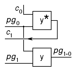
A second handle on the behavior of the propagate signal comes from comparing the original half adder given in Section 2.1 with the carry-lookahead version given here. One consensus consensus gate has been eliminated from the new version. This must be moved into internal nodes of the carry-lookahead tree marked x. These two lines of reasoning lead us to the following design for the nodes of a balanced carry-lookahead tree:
| c1 = ( p0
⊠ c0 )
p1-0 = ( p0 ⊠ p1 ) |
| c4 = ( p3-0 ⊠ c0 ) |
All of the internal nodes in the tree are identical. The labeling in the above figures is specific to the upper right internal node that communicates with the least significant two half adders in the tree and to the root of a 4-trit tree, but the logic does not change for different sized trees. In practice, shallower trees and therefore faster increment circuits will be built by replacing the binary tree given above with a ternary or quaternary tree, limited only by the fan-in of the consensus gates. Here is the internal node design appropriate for a ternary tree:

| c1 = ( p0
⊠ c0 )
c2 = ( p0 ⊠ p1 ⊠ c0 ) p2-0 = ( p0 ⊠ p1 ⊠ p2 ) |
In the abstract, an unsigned carry-lookahead ternary adder stage can be described by the following truth table:
| ||||||||||||||||||||||||||||||||||||
In the above, we have used a mixed notation, using numeric values for the data in and out of each stage of the incrementer, while using Boolean values for carry in to the stage and propagate out from the stage. This mixed notation leads immediately to the conclusion that the carry lookahead logic is identical to that used in a binary increment circuit. In fact, this is true for the unsigned increment function in any number base. Encoding this table using ternary logic, we get the following:
|
|
| ||||||||||||||||||||||||||||||||||||||||||||||||||||||||||||||||||||||||||||||
We can now give give diagrams and formulas for these, in optimal sum-of-products form:
|
pi = ( ai = +1 ) |
The logic for the carry lookahead tree supporting this half adder is nothing new. In the schematic diagrams below, all of the ternary notation that is used is there merely to indicate that the devices used should be ternary compatible. Aside from this, the gates used are simple and gates.
| c1 = ( p0
∧ c0 )
p1-0 = ( p0 ∧ p1 ) |
| c4 = ( p3-0 ∧ c0 ) |
The tree structure shown in the following figure illustrates the classical construciton of a carry-lookahead adder, built along the lines suggested by Rosenberger, 1960.
|
The above figure shows a binary tree, but Rosenberger used a ternary tree, and quatrinary trees have been commonly used with binary adders since the introduction of the 74182 chip in the early 1970s. The leaves of the carry-lookahead tree for a binary adder are modified full adders that produce two auxiliary signals instead of the carry out signal used for ripple-carry adders. The first of these, p, indicates whether that stage of the adder will propagate a carry from its input to its output. This corresponds exactly to the propagate signal used above for a carry-lookahead incrementer. The second, g, indicates whether that stage of the adder will generate a carry independent of the carry in to that stage.
The situation is relatively simple for unsigned addition. Here is the table for unsigned add, using the standard Boolean encoding of propagate, generate and carry used with binary addition:
| ||||||||||||||||||||||||||||||||||||||||||||||||||||||||||||||||||||||||||||||||||||||||||||||||||||||||||||||||||||||||||||
In the above table, note that, when the adder stage generates a carry locally, we don't particularly care about the propagate output. This leads us to a new insight: The propagate and generate signals naturally combine into a single ternary signal that we will call pg:
|
Combining the propagate and generate signals gives us the following simplified tree structure for the lookahead carry logic connecting the stages of an adder:
|
Recoding the table for the adder into a truth table involves two changes. First, we combine the propagate and generate signals, and second, we recode the unsigned 0, 1 and 2 into the balanced notation used for ternary logic throughout this discussion. This allows us to derive an optimal sum-of-products:
|
|
| ||||||||||||||||||||||||||||||||||||||||||||||||||||||||||||||||||||||||||||||||||||||||||||||||||||||||||||||||||||||||||||||||||||||||||||||||||||||||||||||||||||||||||||||||||||||||||||||||||||||||||||||||||||||||||||||||||||||||||||||||
The question of what to do with the don't-care conditions in the above tables will crop up later in this discussion. As we will see, there is some benefit to making ci = 0 equivalent to ci = –1 This leads to the following optimized results, expressed as a circuit diagram and formulas:
|
|
Note that the above equations and logic diagram have not been fully reduced in order to emphasize their relationship to the truth tables from which they were derived. Indicating a constant input of +1 to an min gate, for example, does not actually imply the need for an input to that gate. Given that all other inputs to the min gates in sum-of-products logic are Boolean valued, all such min gates are actually simple Boolean and gates.
In the case of min gates with one input set to the constant 0, where all other inputs are Boolean, we do not need to use ternary logic gates at all. Instead, we can use Boolean logic, with the output clamped into the range -1 to 0 instead of the usual -1 to +1. Thus, all of the min gates in the sum of products are no more complex than conventional Boolean and gates.
Combining propagate and generate signals moving up the tree, half of the logic for the internal nodes (x) in our carry-lookahead tree, can be remarkably simple when propagate and generate are combined as a single ternary function. The truth table is presented below, along with the result of an optimal sum-of-products minimization exercise:
|
| |||||||||||||||||||||||||||||||||||||||||||||||||||
It is highly probable that a simple logic gate can be built that directly implements the above truth table. One avenue to this, for example, would be to compute the analog sum 3
|
|
As with a conventional carry-lookahead Boolean adder, the carry in to the most significant subtree of each vertex will be the same as the carry in to the least significant subtree when the least significant subtree propagates, and it will be true if the least significant subtree generates. If we encode carry as +1 and no carry as either -1 or 0, as already mentioned, the root node (y) of our carry lookahead tree becomes identical to half of an internal node (x), although it can be simplified if the carry in signal never has the value 0. In that case, the gate marked with an asterisk above can be omitted. The full internal node is constructed from two of these:
|
Note that the computation of the carry out of the internal node can also be simplified. The simplified version of the carry lookahead tree's root node (y) discussed above omits a term. In constructing each internal node, the carry in to the most significant subtree of that node can be computed from the carry in to the node using the simplified form, as indicated by the asterisk here.
For adding balanced ternary numbers, an adder stage will propagate a positive carry in if one or both of the addend inputs to that stage are positive (and none are negative), and it will propagate a negative carry if one or both addends are negative (and none are positive). Thus, at stage i, we can compute the propagate output using an accept anything operator:
This looks promising, but all is not well. Given no carry in to a stage, that stage will generate a carry out of +1 if the two addends are both +1, and a carry out of –1 if both addends are –1. Thus, we could use a consensus operator to compute the generate output from stage i of the adder:
Unfortunately, the above paragraph contained the caveat "given no carry in to a stage." In a binary adder, the two addend digits input to a stage of the adder could force a carry out independent of the carry in to that stage. With a balanced ternary adder, the carry in to a stage of the adder can prevent that stage from generating a carry out. Solving this problem requires a more complex encoding than the 3 or 4-valued propagate-generate signals that work for binary and unsigned ternary arithmetic.
There is a high-level discussion of carry-lookahead in binary-coded ternary computers in [Parhami and McKeown, 2013]. They conclude that two copies of a conventional unsigned carry lookahead tree will suffice to build a balanced ternary carry lookahead tree. Here, we note that this bound conforms to the basic insight that balanced ternary is essentially a biased number system, and therefore biased addition can be done by adding the two operands and then adding a bias to the result. Here, we focus on a different approach. Can we directly build a carry lookahead circuit for balanced ternary?
Looking at the recoding we used for the propagate and generate signals for the unsigned ternary adder, we can quickly conclude that each stage of the balanced ternary adder will have the following propagate-generate outputs:
|
|
There is no condition of the inputs that guarantees that a stage in the adder will generate a carry, only that it may generate. For example, if both inputs to a stage are +1, the stage will only generate a carry if the carry in to that stage is not –1. Our challenge with these new signals is to work out how they propagate up the carry lookahead tree, and how carry signals are generated in this tree.
Note that the work we have already done on a ripple-carry balanced adder is still applicable for computing si as a function of ai, bi and ci, so aside from questions of the encoding of pgi, our primary job at this point is to work out the details of the internal nodes of the lookahead tree
At each internal node, two propagate-generate signals encoded as above arrive, one from the left (more significant) subtree, one from the right (less significant) subtree. If the left subtree says M+ and the right subtree says N, then the output from the internal node must indicate that there will, most certainly, be a carry out. Thus, we must add two more values to our encoding:
|
We can now fully define the internal node of the carry anticipation tree in terms of these values with a 7 by 7 table describing how each node computes the propagate-generate signal sent on up the tree and a 7 by 3 table describing how each node computes the carry in to its left subtree from the carry in to the node itself:
|
| |||||||||||||||||||||||||||||||||||||||||||||||||||||||||||||||||||||||||||||||||||||||||||||||||||||||||||||||||||
Two cells the left table above have been shaded. These mark cases where the two subtrees may generate carries of opposite polarity depending on the carry in to that subtree. At first blush, it might look like this is a worst case that prevents carry lookahead, but in fact, there are only two possibilities:
In sum, the net result is that two subtrees that each conditionally generate a carry of opposing sign work together to create a tree that effectively propagates from carry in to carry out, even though that carry is actually adsorbed and another carry of the same sign is regenerated.
It is worth nothing that the diagonal structure of both tables above strongly suggests that these two functions can be computed with threshold logic threshold logic, although threshold logic with 3 or 4 ternary inputs would require setting very finely tuned thresholds. In general, finely tuned thresholds are not good candidates for mass production.
To reduce the above to practical form, we must find an encoding of the seven-valued propagate-generate signal that leads to convenient implementation of the necessary logic. Two ternary signals can encode 9 values, and there are a huge number of ways our 7 values can be mapped onto the 9. Symmetry arguments allow us to eliminate many of them, but the number remains daunting. The following coding is arbitrary and seems reasonable:
|
The labels p and g are used here without the specific meanings propagate and generate, but rather, these names are retained arbitrarily because, taken together, they communicate what in a binary carry-lookahead adder were the propagate and generate signals.
Using the above encoding, we can finish the truth tables for each stage of the adder.
|
|
|
The optimizations shown above require a total of 12 distinct minterms. Note that the work we have already done on a ripple-carry balanced adder shows that it takes 12 minterms to compute si as a function of ai, bi and ci. Thus, we can conclude that it takes 24 minterms for each trit of a balanced carry lookahead adder, plus the logic of the carry lookahead tree itself. This compares with 18 minterms per trit of an unsigned or 3's complement carry lookahead adder.
Using the above encoding, we can write out the truth table for carry in to the left subtree as a function of PG out of the right subtree and the carry in to the entire tree:
|
| |||||||||||||||||||||||||||||||||||||||||||||||||||||||||||||||||||||||||||||||||||||||||||||||||||||||||||||||||||||||||||||||||||||||||||||||||||||||||||||||
Where the optimized carry out computation for an unsigned ternary carry-lookahead tree node had just 2 minterms, the move to balanced ternary seems to have raised the cost to 7 minterms. It may be the case that a different encoding would permit better optimization, but it does not look promising.
The exercise of developing the full tree node is daunting. This involves a function of 4 ternary variables, where the full truth table has 81 rows.
We have demonstrated that ternary addition of two n-trit numbers can be done in O(log n) time. This suggests that ternary computers can compete effectively with binary computers in terms of computation speed, but can they compete in terms of cost? To answer this question, we need to compare the complexity of ternary and binary adders. Here is the truth table for a conventional binary carry-lookahead adder, along with the minimal sum-of-products expressed in the shorthand tabular notation we have used above.
|
|
|
| |||||||||||||||||||||||||||||||||||||||||||||||||||||||||||||||||||||||||||||||||||||||||||||||||||||||||||||||||||||||||||||||
From the above, we note that one bit slice of a conventional binary carry-lookahead adder has 7 minterms when expressed in optimal sum-of-products form (2 for propagate, one for generate and 4 for sum), while the unsigned ternary carry-lookahead adder required 18 minterms (6 for propagate-generate and 12 for sum). In comparing these numbers, we must account for the fact that each ternary trit is worth 1.58 bits. Thus, the ratio that matters is not 7:18 but approximately 11.1:18. The net result is that a ternary computer will generally require on the order of 1.62 times as much logic in its adder as is required by a conventional binary computer of comparable capacity.
Were it not for the fact that hardware has become dirt cheap, this would be discouraging, but the fact is, today's most successful line of CPU chips, the Intel 80x86 family, clearly demonstrates that grossly inefficient use of hardware is not an obstacle to success. Nonetheless, there remains considerable room for improvement in our unsigned ternary adder design.
Finding novel ternary gate designs that avoid reduction to sum-of-products form could significantly improve the standing of ternary in this comparison. Another consideration that may help is the ratio of interconnection to logic on the surface of a chip. Interconnect costs dominate the economics of modern VLSI chip design, so it may be that the factor of 1.58 reduction in interconnection repays the cost of the extra gates required for use of Ternary.
Two different threads of the above discussion combine to allow us to speculate about why we failed in our attempt to develop a balanced ternary carry-lookahead adder: First, we observed that a balanced add could be constructed from an unbalanced add by subtracting the bias from the result. Since subtracting the bias is equivalent to adding the bias plus one, this allows us to conclude that a balanced-ternary adder is equivalent to two unsigned ternary adders, the second of is used to add a constant.
While the carry outputs of each stage of this pair of adders may be correlated, allowing a ripple carry adder to be built using a ternary carry signal, the propagate-generate signals appear to be more more complex. If we simply used a pair of unsigned ternary carry-lookahead adders, with the second one used to add in the constant, we would have two independent propagate-generate signals, one for each adder. This suggests that the composite propagate and generate signals in a balanced ternary carry-lookahead adder could be 9-valued, not 3-valued. More work is needed here.
At this point, it seems possible that a balanced ternary carry-lookahead adder will be more complex than an unsigned ternary carry-lookahead adder, and thus, that further development of ternary computers may not benefit from using the balanced number system.