
3. Basic Stepping Motor Control Circuits
Part of
Stepping Motors
|
This section of the stepper tutorial deals with the basic final stage drive circuitry for stepping motors. This circuitry is centered on a single issue, switching the current in each motor winding on and off, and controlling its direction. The circuitry discussed in this section is connected directly to the motor windings and the motor power supply, and this circuitry is controlled by a digital system that determines when the switches are turned on or off.
This section covers all types of motors, from the elementary circuitry needed to control a variable reluctance motor, to the H-bridge circuitry needed to control a bipolar permanent magnet motor. Each class of drive circuit is illustrated with practical examples, but these examples are not intended as an exhaustive catalog of the commercially available control circuits, nor is the information given here intended to substitute for the information found on the manufacturer's component data sheets for the parts mentioned.
This section only covers the most elementary control circuitry for each class of motor. All of these circuits assume that the motor power supply provides a drive voltage no greater than the motor's rated voltage, and this significantly limits motor performance. The next section, on current limited drive circuitry, covers practical high-performance drive circuits.
Typical controllers for variable reluctance stepping motors are variations on the outline shown in Figure 3.1:
Figure 3.1In Figure 3.1, boxes are used to represent switches; a control unit, not shown, is responsible for providing the control signals to open and close the switches at the appropriate times in order to spin the motors. In many cases, the control unit will be a computer or programmable interface controller, with software directly generating the outputs needed to control the switches, but in other cases, additional control circuitry is introduced, sometimes gratuitously!
Motor windings, solenoids and similar devices are all inductive loads. As such, the current through the motor winding cannot be turned on or off instantaneously without involving infinite voltages! When the switch controlling a motor winding is closed, allowing current to flow, the result of this is a slow rise in current. When the switch controlling a motor winding is opened, the result of this is a voltage spike that can seriously damage the switch unless care is taken to deal with it appropriately.
There are two basic ways of dealing with this voltage spike. One is to bridge the motor winding with a diode, and the other is to bridge the motor winding with a capacitor. Figure 3.2 illustrates both approaches:
Figure 3.2The diode shown in Figure 3.2 must be able to conduct the full current through the motor winding, but it will only conduct briefly each time the switch is turned off, as the current through the winding decays. If relatively slow diodes such as the common 1N400X family are used together with a fast switch, it may be necessary to add a small capacitor in parallel with the diode.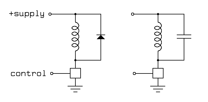
The capacitor shown in Figure 3.2 poses more complex design problems! When the switch is closed, the capacitor will discharge through the switch to ground, and the switch must be able to handle this brief spike of discharge current. A resistor in series with the capacitor or in series with the power supply will limit this current. When the switch is opened, the stored energy in the motor winding will charge the capacitor up to a voltage significantly above the supply voltage, and the switch must be able to tolerate this voltage. To solve for the size of the capacitor, we equate the two formulas for the stored energy in a resonant circuit:
P = C V2 / 2Where:
P = L I2 / 2
P -- stored energy, in watt seconds or coulomb voltsSolving for the minimum size of capacitor required to prevent overvoltage on the switch is fairly easy:
C -- capacity, in farads
V -- voltage across capacitor
L -- inductance of motor winding, in henrys
I -- current through motor winding
C > L I2 / (Vb - Vs)2Where:
Vb -- the breakdown voltage of the switchVariable reluctance motors have variable inductance that depends on the shaft angle. Therefore, worst-case design must be used to select the capacitor. Furthermore, motor inductances are frequently poorly documented, if at all.
Vs -- the supply voltage
The capacitor and motor winding, in combination, form a resonant circuit. If the control system drives the motor at frequencies near the resonant frequency of this circuit, the motor current through the motor windings, and therefore, the torque exerted by the motor, will be quite different from the steady state torque at the nominal operating voltage! The resonant frequency is:
f = 1 / ( 2π (L C)0.5 )Again, the electrical resonant frequency for a variable reluctance motor will depend on shaft angle! When a variable reluctance motors is operated with the exciting pulses near resonance, the oscillating current in the motor winding will lead to a magnetic field that goes to zero at twice the resonant frequency, and this can severely reduce the available torque!
Typical controllers for unipolar stepping motors are variations on the outline shown in Figure 3.3:
Figure 3.3In Figure 3.3, as in Figure 3.1, boxes are used to represent switches; a control unit, not shown, is responsible for providing the control signals to open and close the switches at the appropriate times in order to spin the motors. The control unit is commonly a computer or programmable interface controller, with software directly generating the outputs needed to control the switches.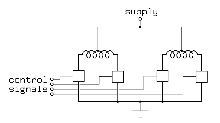
As with drive circuitry for variable reluctance motors, we must deal with the inductive kick produced when each of these switches is turned off. Again, we may shunt the inductive kick using diodes, but now, 4 diodes are required, as shown in Figure 3.4:
Figure 3.4The extra diodes are required because the motor winding is not two independent inductors, it is a single center-tapped inductor with the center tap at a fixed voltage. This acts as an autotransformer! When one end of the motor winding is pulled down, the other end will fly up, and visa versa. When a switch opens, the inductive kickback will drive that end of the motor winding to the positive supply, where it is clamped by the diode. The opposite end will fly downward, and if it was not floating at the supply voltage at the time, it will fall below ground, reversing the voltage across the switch at that end. Some switches are immune to such reversals, but others can be seriously damaged.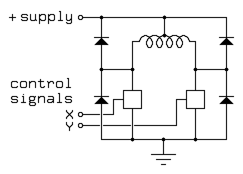
A capacitor may also be used to limit the kickback voltage, as shown in Figure 3.5:
Figure 3.5The rules for sizing the capacitor shown in Figure 3.5 are the same as the rules for sizing the capacitor shown in Figure 3.2, but the effect of resonance is quite different! With a permanent magnet motor, if the capacitor is driven at or near the resonant frequency, the torque will increase to as much as twice the low-speed torque! The resulting torque versus speed curve may be quite complex, as illustrated in Figure 3.6: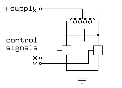
Figure 3.6Figure 3.6 shows a peak in the available torque at the electrical resonant frequency, and a valley at the mechanical resonant frequency. If the electrical resonant frequency is placed appropriately above what would have been the cutoff speed for the motor using a diode-based driver, the effect can be a considerable increase in the effective cutoff speed.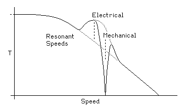
The mechanical resonant frequency depends on the torque, so if the mechanical resonant frequency is anywhere near the electrical resonance, it will be shifted by the electrical resonance! Furthermore, the width of the mechanical resonance depends on the local slope of the torque versus speed curve; if the torque drops with speed, the mechanical resonance will be sharper, while if the torque climbs with speed, it will be broader or even split into multiple resonant frequencies.
In the above circuits, the details of the necessary switches have been deliberately ignored. Any switching technology, from toggle switches to power MOSFETS will work! Figure 3.7 contains some suggestions for implementing each switch, with a motor winding and protection diode included for orientation purposes:
Figure 3.7Each of the switches shown in Figure 3.7 is compatible with a TTL input. The 5 volt supply used for the logic, including the 7407 open-collector driver used in the figure, should be well regulated. The motor power, typically between 5 and 24 volts, needs only minimal regulation. It is worth noting that these power switching circuits are appropriate for driving solenoids, DC motors and other inductive loads as well as for driving stepping motors.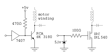
The SK3180 transistor shown in Figure 3.7 is a power darlington with a current gain over 1000; thus, the 10 milliamps flowing through the 470 ohm bias resistor is more than enough to allow the transistor to switch a few amps current through the motor winding. The 7407 buffer used to drive the darlington may be replaced with any high-voltage open collector chip that can sink at least 10 milliamps. In the event that the transistor fails, the high-voltage open collector driver serves to protects the rest of the logic circuitry from the motor power supply.
The IRC IRL540 shown in Figure 3.7 is a power field effect transistor. This can handle currents of up to about 20 amps, and it breaks down nondestructively at 100 volts; as a result, this chip can absorb inductive spikes without protection diodes if it is attached to a large enough heat sink. This transistor has a very fast switching time, so the protection diodes must be comparably fast or bypassed by small capacitors. This is particularly essential with the diodes used to protect the transistor against reverse bias! In the event that the transistor fails, the zener diode and 100 ohm resistor protect the TTL circuitry. The 100 ohm resistor also acts to somewhat slow the switching times on the transistor.
For applications where each motor winding draws under 500 milliamps, the ULN200x family of darlington arrays from Allegro Microsystems, also available as the DS200x from National Semiconductor and as the Motorola MC1413 darlington array will drive multiple motor windings or other inductive loads directly from logic inputs. Figure 3.8 shows the pinout of the widely available ULN2003 chip, an array of 7 darlington transistors with TTL compatible inputs:
Figure 3.8The base resistor on each darlington transistor is matched to standard bipolar TTL outputs. Each NPN darlington is wired with its emitter connected to pin 8, intended as a ground pin, Each transistor in this package is protected by two diodes, one shorting the emitter to the collector, protecting against reverse voltages across the transistor, and one connecting the collector to pin 9; if pin 9 is wired to the positive motor supply, this diode will protect the transistor against inductive spikes.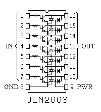
The ULN2803 chip is essentially the same as the ULN2003 chip described above, except that it is in an 18-pin package, and contains 8 darlingtons, allowing one chip to be used to drive a pair of common unipolar permanent-magnet or variable-reluctance motors.
For motors drawing under 600 milliamps per winding, the UDN2547B quad power driver made by Allegro Microsystems will handle all 4 windings of common unipolar stepping motors. For motors drawing under 300 milliamps per winding, Texas Instruments SN7541, 7542 and 7543 dual power drivers are a good choice; both of these alternatives include some logic with the power drivers.
Things are more complex for bipolar permanent magnet stepping motors because these have no center taps on their windings. Therefore, to reverse the direction of the field produced by a motor winding, we need to reverse the current through the winding. We could use a double-pole double throw switch to do this electromechanically; the electronic equivalent of such a switch is called an H-bridge and is outlined in Figure 3.9:
Figure 3.9As with the unipolar drive circuits discussed previously, the switches used in the H-bridge must be protected from the voltage spikes caused by turning the power off in a motor winding. This is usually done with diodes, as shown in Figure 3.9.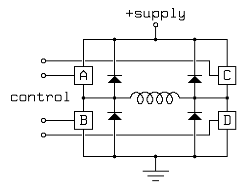
It is worth noting that H-bridges are applicable not only to the control of bipolar stepping motors, but also to the control of DC motors, push-pull solenoids (those with permanent magnet plungers) and many other applications.
With 4 switches, the basic H-bridge offers 16 possible operating modes, 7 of which short out the power supply! The following operating modes are of interest:
Figure 3.10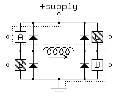
Figure 3.11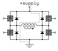
Figure 3.12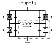
Figure 3.13Here, the following operating modes are available: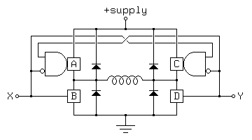
The advantage of this arrangement is that all of the useful operating modes are preserved, and they are encoded with a minimum number of bits; the latter is important when using a microcontroller or computer system to drive the H-bridge because many such systems have only limited numbers of bits available for parallel output. Sadly, few of the integrated H-bridge chips on the market have such a simple control scheme.
XY ABCD Mode 00 0000 fast decay 01 1001 forward 10 0110 reverse 11 0101 slow decay
There are a number of integrated H-bridge drivers on the market, but it is still useful to look at discrete component implementations for an understanding of how an H-bridge works. Antonio Raposo (ajr@cybill.inesc.pt) suggested the H-bridge circuit shown in Figure 3.14;
Figure 3.14The X and Y inputs to this circuit can be driven by open collector TTL outputs as in the darlington-based unipolar drive circuit in Figure 3.7. The motor winding will be energised if exactly one of the X and Y inputs is high and exactly one of them is low. If both are low, both pull-down transistors will be off. If both are high, both pull-up transistors will be off. As a result, this simple circuit puts the motor in dynamic braking mode in both the 11 and 00 states, and does not offer a coasting mode.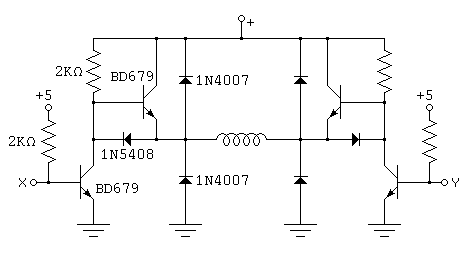
The circuit in Figure 3.14 consists of two identical halves, each of which may be properly described as a push-pull driver. The term half H-bridge is sometimes applied to these circuits! It is also worth noting that a half H-bridge has a circuit quite similar to the output drive circuit used in TTL logic. In fact, TTL tri-state line drivers such as the 74LS125A and the 74LS244 can be used as half H-bridges for small loads, as illustrated in Figure 3.15:
Figure 3.15This circuit is effective for driving motors with up to about 50 ohms per winding at voltages up to about 4.5 volts using a 5 volt supply. Each tri-state buffer in the LS244 can sink about twice the current it can source, and the internal resistance of the buffers is sufficient, when sourcing current, to evenly divide the current between the drivers that are run in parallel. This motor drive allows for all of the useful states achieved by the driver in Figure 3.13, but these states are not encoded as efficiently: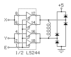
The second dynamic braking mode, XYE=110, provides a slightly weaker braking effect than the first because of the fact that the LS244 drivers can sink more current than they can source.
XYE Mode --1 fast decay 000 slower decay 010 forward 100 reverse 110 slow decay
The Microchip (formerly Telcom Semiconductor) TC4467 Quad CMOS driver is another example of a general purpose driver that can be used as 4 independent half H-bridges. Unlike earlier drivers, the data sheet for this driver even suggests using it for motor control applicatons, with supply voltages up to 18 volts and up to 250 milliamps per motor winding.
One of the problems with commercially available stepping motor control chips is that many of them have relatively short market lifetimes. For example, the Seagate IPxMxx series of dual H-bridge chips (IP1M10 through IP3M12) were very well thought out, but unfortunately, it appears that Seagate only made these when they used stepping motors for head positioning in Seagate disk drives. The Toshiba TA7279 dual H-bridge driver would be another another excellent choice for motors under 1 amp, but again, it appears to have been made for internal use only.
The SGS-Thompson (and others) L293 dual H-bridge is a close competitor for the above chips, but unlike them, it does not include protection diodes. The L293D chip, introduced later, is pin compatible and includes these diodes. If the earlier L293 is used, each motor winding must be set across a bridge rectifier (1N4001 equivalent). The use of external diodes allows a series resistor to be put in the current recirculation path to speed the decay of the current in a motor winding when it is turned off; this may be desirable in some applications. The L293 family offers excellent choices for driving small bipolar steppers drawing up to one amp per motor winding at up to 36 volts. Figure 3.16 shows the pinout common to the L293B and L293D chips:
Figure 3.16This chip may be viewed as 4 independent half H-bridges, enabled in pairs, or as two full H-bridges. This is a power DIP package, with pins 4, 5, 12 and 13 designed to conduct heat to the PC board or to an external heat sink.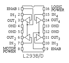
The SGS-Thompson (and others) L298 dual H-bridge is quite similar to the above, but is able to handle up to 2-amps per channel and is packaged as a power component; as with the LS244, it is safe to wire the two H-bridges in the L298 package into one 4-amp H-bridge (the data sheet for this chip provides specific advice on how to do this). One warning is appropriate concerning the L298; this chip very fast switches, fast enough that commonplace protection diodes (1N400X equivalent) don't work. Instead, use a diode such as the BYV27. The National Semiconductor LMD18200 H-bridge is another good example; this handles up to 3 amps and has integral protection diodes.
While integrated H-bridges are not available for very high currents or very high voltages, there are well designed components on the market to simplify the construction of H-bridges from discrete switches. For example, International Rectifier sells a line of half H-bridge drivers; two of these chips plus 4 MOSFET switching transistors suffice to build an H-bridge. The IR2101, IR2102 and IR2103 are basic half H-bridge drivers. Each of these chips has 2 logic inputs to directly control the two switching transistors on one leg of an H-bridge. The IR2104 and IR2111 have similar output-side logic for controlling the switches of an H-bridge, but they also include input-side logic that, in some applications, may reduce the need for external logic. In particular, the 2104 includes an enable input, so that 4 2104 chips plus 8 switching transistors can replace an L293 with no need for additional logic.
The data sheet for the Microchip (formerly Telcom Semiconductor) TC4467 family of quad CMOS drivers includes information on how to use drivers in this family to drive the power MOSFETs of H-bridges running at up to 15 volts.
A number of manufacturers make complex H-bridge chips that include current limiting circuitry; these are the subject of the next section. It is also worth noting that there are a number of 3-phase bridge drivers on the market, appropriate for driving Y or delta configured 3-phase permanent magnet steppers. Few such motors are available, and these chips were not developed with steppers in mind. Nonetheless, the Toshiba TA7288P, the GL7438, the TA8400 and TA8405 are clean designs, and 2 such chips, with one of the 6 half-bridges ignored, will cleanly control a 5-winding 10 step per revolution motor.