Counting Mark-Sense BallotsRelating Technology, the Law and Common Sense
Part of
the Voting and Elections web pages
Copyright © 2002, minor revisions 2003. This work may be transmitted or stored in electronic form on any computer attached to the Internet or World Wide Web so long as this notice is included in the copy. Individuals may make single copies for their own use. All other rights are reserved. |
|
The mathemagician nodded knowingly and stroked his chin several times. "You'll find," he remarked gently, "that the only thing you can do easily is be wrong, and that's hardly worth the effort." From The Phantom Tollbooth by Norton Juster |
The problem of interpreting voter intent when hand counting paper ballots has led many people, over the past century, to press for the use of impartial machinery in all ballot counting. The following quotations from the recount battles following the controversial Florida presidential election in the year 2000 expresses this in a very typical ways:
Voting machines are not Republican and are not Democratic, and are not subject to conscious or unconscious bias.James Baker, as quoted by CNN on Nov. 12, 2000.
... I refer to this vote counting model as the "machine model," because it counts as valid only those votes that the vote tabulating machine can read and record. The machine model thus relies on an objective tabulating machine that admits of no discretion to count votes - if a vote is properly cast according to the instructions given to the voter, the machine will count it.Certainly voting machines are not subject to conscious bias because, simply put, they are not conscious! Even the term unconscious bias does not apply because we are reluctant to attribute unconscious behavior to things that are incapable of conscious behavior. What I assert here is that the mechanical vote tabulating systems in use today have variability in their vote counting that is comparable to a degree of discretion and that, as a consequence, the machine model is not an appropriate basis for answering the question of what constitutes a valid vote on an optical mark-sense ballot.U.S. Court of Appeals, 11th Circuit, Dec. 6, 2000, Touchston and Shepperd vs. Michael McDermott
The comparison of vote counting systems and gambling machines provides some useful insight. Gambling machines, even such trivial machines as dice, can certainly be biased. Such biases can be accidental, the result of imperfect construction, or, as in the case of loaded dice, they may be deliberate. A voting machine may be biased in exactly the same ways!
In the remainder of this work, I will discuss the evolution of mark-sense ballot scanning systems and the problems this technology poses, and then I will compare some of the alternative legal models for regulating this technology before proposing my own recommendations. I want to emphasize that mark-sense ballot tabulation remains one of the most reliable of voting technologies despite the technical and legal problems that I will be emphasizing! The number of votes brought into question by the problems pointed out here is likely to be well below one percent of the vote in a properly administered election.

|
- voting target
- The space on a ballot reserved for marks made by the voter in order to indicate a particular preference with regard to an issue on the ballot.
- prescribed mark
- The form of mark a voter is instructed to make in the voting target in order to cast a vote.
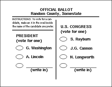
On the classic Australian ballot, the voting targets were either square boxes or circles next to the name of each candidate, and the prescribed mark was an X. When designed for use with optical mark-sense scanners, the target is typically an oval or a broken arrow, and the prescribed mark is either a blot filling the oval or a line connecting the two halves of the broken arrow. The following instructions for making a prescribed mark are typical of those used for hand-counted Australian ballots:
168.576 Marking ballot ...Sec. 576. (1) An elector, after having received a ballot or ballots, shall enter a booth or voting compartment and, while there concealed from view, shall vote the ballot or ballots by making a cross or a check mark in the square at the left of the names of those candidates for whom the elector desires to vote ...
Michigan Election Law, Chapter 168, Section 576, Act 116 of 1954, as amended through 1996.
When counting ballots, we do not limit our count to ballots containing prescribed marks; instead, we count those containing acceptable marks.
- acceptable mark
- Any mark on a ballot that meets the legal requirements to be counted as a vote.
Obviously, under any reasonable code of law, voters who follows the instructions for making a prescribed mark should automatically produce acceptable marks, but the prescription does not usually delimit all of the forms of marking that are and are not acceptable. The Michigan code cited above illustrates this; while voters can easily follow these instructions, when it comes time to count the votes, the vote counters must have answers to these questions:
168.803 Counting and recounting of votes ...Sec. 803. (1) Except as otherwise provided in this act, the following rules shall govern the counting and recounting of votes: ...
(b) A cross, the intersection of which is within or on the line of the proper circle or square, or a check mark, the angle of which is within a circle or square, is valid. Crosses or check marks otherwise located on the ballot are void.
(c) Marks other than crosses or check marks used to designate the intention of the voter shall not be counted.
(d) A cross is valid even though 1 or both lines of the cross are duplicated, if the lines intersect within or on the line of the square or circle.
(e) Two lines meeting within or on the line of the square or circle, although not crossing each other, are valid if it is apparent that the voter intended to make a cross. ...
Michigan Election Law, Chapter 168, Section 803, Act 116 of 1954, as amended through 1997.
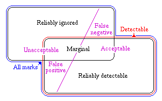
If the instructions for making the ballot are typical of those for optical mark-sense ballots, to fill in the oval next to the candidate's name using black ink or pencil, we must answer a different set of questions. For example, we might be tempted to ask:
|
- detectable mark
- A mark on a ballot that can be detected as a vote by a vote tabulating machine.
- reliably detectable mark
- The form of mark on a ballot that will be detected and counted each and every time the ballot is run through a tabulating machine, irrespective of which voting target is being marked, and irrespective of the particular machine being used.
- reliably ignored mark
- The form of mark on a ballot that will never be detected or counted no matter when the ballot is run through a tabulating machine, irrespective of which voting target is being marked, and irrespective of the particular machine being used.
- marginal mark
- A mark on a ballot that may or may not be counted, depending on which voting target is marked, depending on what vote tabulating machine is used, and depending on when the count is made.
Well formulated voting laws governing the use of machine-counted ballots ensure that the prescribed mark will be reliably detected, and they ensure that, in practice, the vast majority of acceptable marks are reliably detectable and that the vast majority of reliably detectable marks are acceptable.
The machine model, as defined in Touchston and Shepperd vs. McDermott identifies acceptable marks with detectable marks, and it assumes that there will be no marginal marks. Equivalently, it assumes that all detectable marks are reliably detectable. Furthermore, this model is only just if the voter can easily determine, by eye, whether his or her mark is detectable. As we will see, all of these assumptions are false!
No technology based on machine-counted Australian secret ballots can eliminate all marginal marks, and with many voting systems, visual inspection by the person making the mark is not sufficient to determine if the mark will or will not be detectable! We must, therefore, allow for the possibility of marks that are false positives and false negatives. These are standard statistical terms, but in the context of vote counting, we may define these terms for misinterpreted marks as follows:
- false positive mark
- A mark on a ballot that does not meet the legal definition of an acceptable mark but that is, on some occasion, detected by a vote tabulating machine as a vote. False positive marks may be marginal marks or reliably detectable marks.
- false negative mark
- A mark on a ballot that meets the legal definition of an acceptable mark but that is, on some occasion, not detected by a vote tabulating machine. False negative marks may be marginal marks or they may be reliably ignored.
- misinterpreted mark
- A mark on a ballot that is misinterpreted by a vote tabulating machine; this term includes both false positive and false negative marks.
Ideally, we would hope for vote tabulating machines that guaranteed that there would be no marginal marks, no false positive marks and no false negative marks. Unfortunately, there is no technology for machine tabulation of Australian secret ballots that can accomplish this, for two different reasons! First, no technology can eliminate the possibility of a marginal mark, and second, mark-sensing machinery cannot generally duplicate the judgement of a human examining the ballot. To understand these two limitations, we need to understand something about mark sensing technology.
The original mark-sensing technology dates back to the 19th century, when it was developed for use with the very earliest of facsimilie machines; these relied on the ability of the fax scanner to detect the electrical conductivity of marks on the surface. First, this was done with insulating ink on conductive stationary -- they actually used tinfoil stationary in some early systems. In 1937, IBM introduced the Type 805 Test Scoring Machine for processing standardized educational tests, and shortly after this, they began to offer mark-sense options on punched-card forms used in business applications. These systems used the slight electrical conductivity of pencil marks on paper to detect marks. The very first mark-sense ballots, tried in Kern City, California, in 1962, may have used electrical mark-sensing, but I have been unable to find details about these early trials.
Optical mark-sensing also dates back to the facsimilie machine, and by the 1920's, it had been developed to the point that grey-scale photographs could be reliably transmitted by telephone and radio. In the 1950's, a group working under Professor E. F. Lindquist at the University of Iowa developed an optical mark-sense scanning system to score the ACT college entrance examination, and this scanner is the ancestor of the experimental mark-sense scanners used for vote counting by Westinghouse Learning Corporation in the 1970's. American Information Systems, an ancestor of Election Systems and Software, licenced this technology from Westinghouse when the former abandoned this venture.
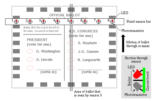
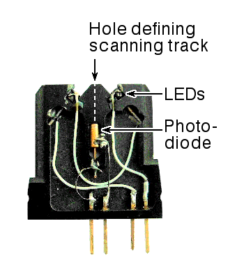
The first generation of mark-sense scanners used for vote counting use infrared light. Such a scanner has an array of sensors, typically packed on 1/4 inch or 1/2 inch centers, but sometimes fewer. Each sensor consists of an infra-red light-emitting diode and phototransistor, matched to each other so that the peak sensitivity of the phototransistor is close to the wavelength emitted by the diode. Typically, the light-emitting diode and phototransistor are mounted side-by-side with a barrier between them so that the only light reaching the photosensor will be that reflected from the ballot. The ballot feed mechanism inside the ballot scanner feeds the ballot past the sensor array in such a way that some sensor in the array scans down each column of voting targets on the ballot. The Election Systems and Software Models 550 and 650 optical mark-sense ballot tabulating machines are typical of this class of scanners, although unlike the illustration in Figure 3, they use fiber optics between the light-emitting diodes, the photosensors and the ballot. Chatsworth Data Corporation also makes scanners that are similar the illustration in Figure 3.
|
|
Note that the voting targets on infrared optical-scan ballots are typically printed in a carefully selected ink that is invisible to the sensors; in visible light, this ink frequently appears red, as shown in Figure 3. Typical scanners have sensors over many different columns of potential voting targets, both because of the evolution of such scanners from test grading machines, and because the extra sensors allow more flexible ballot layouts, for example, allowing the voting targets to be to the left or right of the candidate names and allowing the ballot to be arranged in two or three columns.
In addition to the sensors over the columns of voting targets on the ballot, the machine typically has one or two sensors that detect index marks on one or both edges of the ballot; these are needed because the machine cannot see the voting target itself, so it uses the index marks on the edge to tell it when it is looking at a row of potential voting targets. Additional index marks on the top and bottom are used to detect misaligned ballots; only if all of these marks are seen does the scanner consider the ballot to be correctly aligned.
The area of the ballot seen by each sensor is a narrow stripe running along
the direction of ballot motion through the scanner. Although these areas are
shown with sharp borders in Figure 3, the areas seen by
real sensors usually have diffuse borders. As a result, each sensor
is usually most sensitive to marks that include the center of the stripe it
sees, and less sensitive to marks falling to the sides. In
formal mathematical terms, the sensing profile is typically described by
something close to a Gaussian function.
|
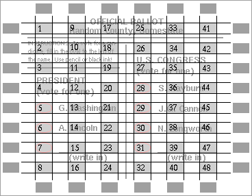
The most common form of voting target printed on the ballot is an oval, but the actual area that the scanner sees on any particular scan of the ballot is the rectangular intersection of the area scanned by one sensor and the row defined by the index marks! Perfect mechanical alignment is impossible, so from one scan of the ballot to the next, the sensor may follow a slightly different path across the ballot. All of the possible paths of the sensors across the ballot typically required to be within the area defined by the index marks at the top and bottom of each column, so the effective voting targets are the rectangular areas at the intersection of the rows and columns defined by the index marks. These are shaded in Figure 5.
Typically, we number the potential voting targets by counting down the columns, leftmost column first, as shown in Figure 5. The scanner hardware actually detects any mark in any voting target, and it is up to the vote tabulating software to ignore marks in the targets that are not part of this election. In the example shown in the figure, only positions 5 through 7 and 28 through 31 are relevant. It is very likely that a scan of the example ballot will detect marks in positions 13 and 21, because the name "Washington" passes through these, but the software should ignore this!
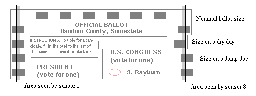
It is worth noting that paper ballots change size slightly with changes in humidity! Commercial printers use the rule of thumb that a 10% increase in relative humidity causes paper to expand by about by one part in 1000; as a result, the size of a piece of bone-dry paper could expand by as much as 1% as it picks up moisture in an extremely humid environment. This comes to 1/10 inch in 10 inches, while many mark-sense voting targets are about 1/8 inch in their short dimension!
The early mark-sense scanners used for scoring tests solved the problems
caused by humidity changes by storing all test papers in a controlled
atmosphere for some time prior to tabulation, but on modern mark-sense vote
tabulators, the design accommodates humidity changes by spacing the
sensors to the midrange of variation in paper size and using voting targets
that are wider than the sensors.
|
If one or more of the top or bottom index marks are not seen on a pass through the scanner, the scanner typically stops with an error message indicating a misfeed. This could be due to an extreme dimensional change in a ballot, for example, because the humidity is too high for reliable scanning or because the paper has been crumpled and then flattened, or it could be because the paper passed through the scanner on a diagonal.
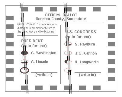
The fact that sensing tracks are narrower than the voting target means that a mark may be seen on one pass through the scanner and not on a later pass, perhaps because of a humidity change from one pass to the next. The fact that a ballot may be on a slight diagonal as it is scanned introduces the possibility that identical marks in two different places on the ballot might be counted differently, even when they are seen by the exact same photosensor.
|
Several marks have been made on the ballot shown in Figure 7 to illustrate some of the marginal marks that are possible because of the geometry of the ballots and photosensors:
|
Conclusion: The fraction of the target area filled in by the voter does not necessarily determine which marks will be counted on a particular mark-sense ballot tabulating machine; in fact, many machines will detect and count some marks that are entirely outside of the target printed on the ballot. Conclusion: It is quite possible for a ballot to be counted in two different ways on two successive passes through the same voting machine. |
|
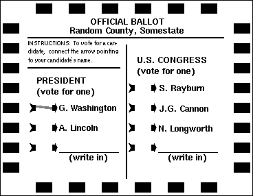
The example ballot shown in Figure 8 is entirely interchangeable with
the example used in the previous figures in the sense that it could be
scanned on the same ballot scanners with no change to the ballot
tabulating software. The only differences between these styles of
voting target lie in the area of human factors. While the oval target is
familiar from other domains such as educational testing, the broken arrow
was found by some early users to invite fewer marginal marks from voters.
Whether this remains true today and whether it is relevant with more
modern scanning mechanisms is not clear.
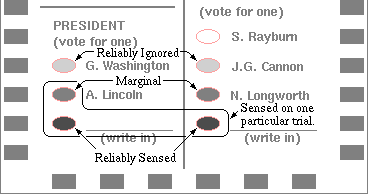
Each particular sensor in a mark sensing scanner will have a threshold. Marks that are below this threshold will not be sensed by this sensor, while marks above this threshold will be sensed. It is also theoretically possible that there will be marks that are just at this threshold, but this possibility does not produce a significant number of marginal marks.
The two primary problems leading to marginal marks that can be traced to sensor thresholds are as follows:
|
More recently, discrete sensor systems have been designed that are self calibrating. These typically compare the darkness of black index marks with the brightness of the adjacent paper as they scan each ballot, and then set the threshold to an appropriate intermediate point between these. The newest central count mark-sense scanners from Election Systems and Software use this approach. An even better approach would be to print, on each ballot, calibration marks that are just above and just below the threshold. With widely available electronics, this approach can be used to calibrate things to within about 1 part in 250, and with modestly more expensive electronics, it can be used to calibrate the sensors to within about 1 part in 4000.
|
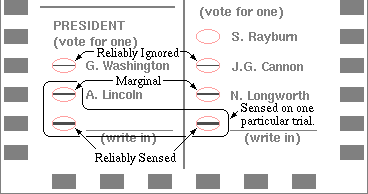
It should be noted that each sensor in a discrete sensor optical mark-sense scanner has two different thresholds, one for the darkness of the mark and one for the width of the mark. Both dark narrow marks and broader light marks may be acceptable. The relation between these two is usually not simple; rather, the darkness required is usually set at such a level that a broad smudge resulting from a poor erasure will not be seen as a mark, while the scanner will usually detect and count a single dark pencil stroke across the marking area.
Note that all of the marks shown in Figure 10 are of identical darkness, and
are as dark as the darkest marks in Figure 9. Had these marks been of marginal
darkness, only the widest would be likely to be sensed at all.
|
Conclusion: Neither the darkness of the mark nor the width of the mark, taken alone, determine which marks will be counted on a particular mark-sense vote tabulating machine. |
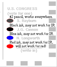
The fundamental problem with infra-red mark sense scanners is that they sense marks using a wavelength of light that the human eye cannot see! As a result, some marks that are clearly evident to the human eye will be invisible to the photosensors in the scanner, while other marks may well be visible to the photosensors but invisible to the human eye!
|
If voters always voted using the marking device provided at the polling place, this would not lead to problems, but absentee voters frequently reach for any available pen or pencil, and if the point breaks off of the pencil provided in the voting booth, voters will frequently use their own pens or pencils, particularly when lines are long and the polling place officials are harried.
The solution is obvious! We can replace the infra-red light-emitting diodes and phototransistors in the mark sensor with light-emitting diodes and photosensors that work with visible light. Reliable red light-emitting diodes and phototransistors sensitive to red light were available within a few years of the original generation of infrared sensors, and like infra-red sensors, these are generally insensitive to light red ink, allowing the scanner to easily ignore the printed red voting targets while reliably sensing marks made by the voter.
The documentation for the mark-sense readers from Chatsworth is quite open about the impact of the shift from infra-red to visible illumination; the data-sheets for all of their standard readers end with a footnote saying: "The I.R. option limits the marking instruments but allows for greater selection of background colors for printing. The Visible Red option allows for a greater range of marking instruments but limits the background printing to a 'Warm Red' color." Few vendors of voting systems have traditionally given this much detail.
Curiously, the very first generation of optical mark-sense scanners used
for scoring the ACT exam in the 1950's used white light from conventional
incandescent lamps. The
problem with incandescent lamps is that they burn out too frequently,
and as a result, only when white LEDs came on the market did some
optical mark-sense scanners return to the use of white light.
|
Conclusion: The apparent darkness of a mark, as seen by the human eye, does not necessarily determine whether that mark will be counted on a particular mark-sense vote tabulating machine. |
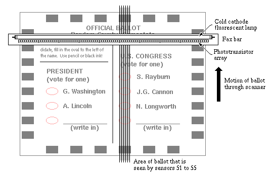
The advent of inexpensive facsimilie machines in the 1980's opened a new path to mark-sense tabulation. from Alexander Bain's first fax machine in 1843 to the present, all fax machines have incorporated page scanning mechanisms of some sort. In the new generation of inexpensive fax machines introduced in the late 20th century, the scanning mechanism is packaged as a fax bar, or more formally as a contact image sensor. The fax bar consists of a linear array of integrated circuit photosensors plus a source of illumination for the copy being scanned. The fax bars used in facsimilie machines typically have close to 200 photosensors per inch; similar sensor arrays made specifically for scanning mark-sense documents are available with resolutions closer to 16 per inch.
|
Typical modern fax bars include either a cold cathode fluorescent lamp or an array of light emitting diodes for illumination. When light emitting diodes are used, they are usually green because green is a rare ink color; black, blue and red are far more common. The cold-cathode lamps used in fax bars are very small, 1/8 inch diameter is typical, and they produce the same quality of white light associated with common household fluorescent lamps. As a result, fax bars are typically able to sense those marks that most people would judge to be intentional.
|
|
At a low level, the sensors used in fax bars report the brightness of each pixel in the document, but because today's facsimilie machines do not transmit the brightness of each pixel, this information is frequently simplified to a simple indication of black and white before the pixel data is given to the computer. For each column of pixels, we can therefore find the brightness threshold above which the sensor will report no mark, and below which it will report that there is a mark.
Because we are using visible light sensors, most fax bars on today's market are able to see voting targets printed in colors such as red, although some cannot sense a light shade of pink or green (depending on the color of LED used in the fax bar). In the example in Figure 13, we have assumed that the sensors are sensitive to the shade of ink used in the voting target, and as a result, blank voting targets are seen by the scanner as having around 14 dark pixels. In contrast, the marked target shown in the figure has 27 dark pixels.
The number of pixels reported as being dark when scanning any particular mark on the ballot may vary from one scan to the next depending on how the grid of pixels happens to align with the mark. Shifting the mark half a pixel left, right, up or down may add or subtract a few pixels from the total. As a result, some scans of an unmarked voting target might show as few as 12 pixels, while others might show as many as 16 pixels.
Given that our example marked target has 27 dark pixels and our example
unmarked target has only 14 dark pixels, an obvious strategy to use in with
this scanning system is to declare a voting target to be voted if more than,
say, 18 pixels in the vicinity of the target are found to be dark. Such a
threshold strategy requires no attempt at complex image analysis! All
that is needed is software in the voting system that finds the
index marks, and then using that information, finds the locations on the ballot
where voting targets are expected.
|
Conclusion: The use of advanced technologies such as visible light sensing and fax bars cannot eliminate the class of marginal marks; at best, such technologies can reduce the number of marks that might be marginal. |
The threshold method outlined here is probably typical of today's ballot scanners, but it is important to emphasize that voting system manufacturers generally do not reveal anything about how their scanners identify marks! Frequently, the publically available documentation on the scanners does not even reveal whether they use discrete sensors or fax bars.
The Election Systems and Software PBC 100 precinct-count optical mark-sense ballot tabulating machine is an exception. This machine is advertised as using an intelligent mark recognition algorithm based on image processing. For classical elliptical voting targets, this algorithm uses exactly the kind of pixel-counting threshold method documented here; for Optech-style broken arrow voting targets, it takes advantage of the boldly printed half-arrows by using them as index marks to locate the precise top and bottom bounds of each voting target.
These relatively crude schemes for identifying marks on the ballot using a fax bar scanner are generally significantly better at reading the ballot than a discrete sensor scanner. They can easily distinguish between small dots in the voting area and a line crossing the target in any direction, and they are generally insensitive to the direction of the line. Because the designers of fax bars are very sensitive to the requirements of fax machines, these sensors are generally good at reading any reasonable weight of pencil stroke or any common shade of ink, and they are generally good at ignoring all but the worst erasures.
In theory, it would be possible to use advanced computer-based image processing methods to do even better. Imagine software that located the voting target and all marks near it on the ballot using image processing techniques and then classified the marks as spots, pen or pencil strokes, or other marks. Having located the apparent pen and pencil strokes, the software would then classify them as dashes, checks, Xs, etc before applying a standard derived from the applicable law in order to determine which are votes.
One problem with the use of such advanced image processing algorithms is that most voting system manufacturers do not have the necessary expertise to oversee development of such software. Furthermore, the inclusion of such complex software in a voting system significantly increases the difficulty of certifying the software for the voting application.
The different sensors in a fax bar or similar scanning system generally have different thresholds! This is an unavoidable consequence of the integrated circuit manufacturing process used to make the sensors, and unlike scanners that use discrete sensors, we can do little to calibrate the sensors in the fax bar. Instead, we rely on the fact that each voting target is seen by a large number of sensors; for example, the low resolution scanner in Figure 12 sees each target with 6 or 7 sensors, depending on how the ballot is aligned. So long as the variations in sensor threshold are random, the more sensors that see each voting target, the more likely it is that each voting target will be seen with a similar range of sensor thresholds.
|
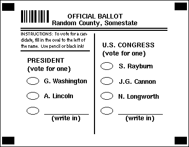
Figure 14 illustrates a ballot design appropriate for such an environment. Here, instead of marking each row and column with index marks, the ballot contains only four special marks, in the extreme corners of the ballot. Such marks are called fiducial marks. The software used to interpret the pixelized image of the ballot first locates these fiducial marks and then measures from these in order to locate the voting targets. This approach can easily correct for ballots that are fed into the scanner on a diagonal and it can correct for uniform changes in ballot dimensions caused by humidity.
Another common feature found on ballots designed to be read on fax bar scanners or other scanners that pixelize the image prior to processing is a bar code to identify, for example, the precinct or ballot style. Simple codes for identifying this information have been used with older generations of ballot scanning systems, for example, by using wide and narrow index marks along the top or bottom rows of the ballot, or by reserving a column of the ballot for a code track, as is usually done on the Election Systems and Software Models 550 and 650 optical mark-sense ballot tabulating systems.
It is important to note that the developers of ballot tabulators that use fax bars or other image sensing technologies generally work to maintain compatibility with earlier discrete scan mark sensors. While it would be possible, in theory, to build an image sensing mark-sense tabulators that requires a very accurate reproduction of the prescribed mark, in general, this is not done. If it were done, the new tabulating system would reject votes that were accepted by the earlier tabulating system, and this would be unacceptable to most jurisdictions.
Today, fax bars are in competition with an even higher performance class of scanning mechanisms, those designed for image scanning. Todays image scanning mechanisms have resolutions of 300 pixels per inch or more, and with complete scanners available at costs of under $100, it is not surprising to find these being incorporated into new ballot tabulators.
Aside from a higher resolution, the most important feature of image scanning mechanisms is that they deliver either an overall brightness report for each pixel, in the case of black and white scanners, or separate red, green and blue brightness reports for each pixel in the case of color scanners. Given brightness reports for each pixel, the software can easily compare the paper background to the index marks in order to calibrate the sensors for the extremes of black and white found on the ballot. The ballot shown in Figure 14 has no index marks, but the heavy horizontal line that separates the ballot heading from the body of the ballot can serve exactly the same purpose.
With color scanners, it is possible, in theory, to distinguish between special inks and the colors of pen or pencil that are required, but I have seen no evidence that the voting systems on the market today are doing this. As with fax bar scanners, however, the vendors do not generally disclose to the states the actual method they use to distinguish between marked and unmarked voting targets.
|
Conclusion: The exact same ballot format may be used with a variety of different mark-sense ballot tabulating machines, where the different tabulating machines count marks in distinctly different ways, applying different criteria to determining which marks are and are not counted as votes. |
There are several sources of false positives that plague all optical mark-sense scanners. The most important of these are the result of ballot defects. The following types of ballot defects are relatively rare, but all of them occur occasionally.
- Printing errors
- All printing processes produce occasional smudges and ink splatters. Small defects the size of a pencil mark can easily escape the kind of quality control methods traditional in the printing industry, yet if these accidentally fall in a voting target, they can be read as a vote by the scanner.
- Defects in the paper
- Ballots are usually printed on relatively high quality paper or lightweight cardstock, but this does not guarantee that the paper will be free of defects. The most common defects found in such paper are flecks of foreign material, usually a light brown color. If such a fleck occurs in a voting target, it can be read as a vote by the scanner.
If we demanded that all ballots be scanned prior to issue to the voter and we reject any that contain votes on this preliminary scan, we would eliminate the few ballots that are accidentally pre-marked in the manufacturing process, but there are other sources of marks that make such a precaution largely irrelevant.
- Accidents
- Whenever people handle pieces of paper, there is the possibility that they will leave marks. Generally, ballots are handled by at least two people at the polling place, the voter and the worker who hands the ballot to the voter. In central count systems and absentee voting, even more hands typically touch each ballot. While we can ask everyone involved to work with clean hands, there is still the possibility that, for example, a pencil point will break somewhere nearby and that a ballot or stack of ballots will be set down on the broken pencil point, leaving a mark.
- Hesitation marks
- One particular class of accidental mark is of special importance. Many people, when holding a pencil while reading a text, use the pencil point as a pointer, resting it on the paper beside each line while reading that line. Unfortunately, wherever the voter rests the pencil point, it will generally make a faint mark, and the obvious place to rest the pencil point beside a line on the ballot is in the voting target for that line.
Most accidental marks are small spots, and most mark-sense ballot tabulating systems have thresholds set so that they ignore typical hesitation marks, but some voters make darker hesitation marks than others. Voters with mild vision problems frequently find it helpful to use a pointer when reading, and the same mild vision problem that leads a voter to use the pencil as a pointer may make that voter unable to see the marks it leaves.
The instructions forbidding erasure are frequently quite blunt, sometimes to the extent that some voters may believe that erasures actually invalidate their ballots.
- Erasures
- While the instructions frequently prohibit erasures, most mark-sense vote tabulating machines are fairly good at disregarding cleanly erased marks. Some erasures, however, are dark enough that they will be read as a mark.
Do not erase or cross out. Obtain a new ballot if you make an error.
Official Ballot, General Election, Nov 7, 2000, Walton County, Florida.
Unfortunately, while it is easy to state a prohibition against erasure or correction, it is extremely difficult to enforce it. At a polling place where the lines are long and the polling place officials are harried, voters may hesitate to ask for replacement ballots and instead opt to erase, and it may be completely impossible for an absentee voter to obtain a replacement ballot.
|
Conclusion: If erasures are forbidden by law, we must face the fact that most of the available mark-sense vote tabulating systems will disregard most competently made erasures. If, on the other hand, we allow erasure, we must face the fact that some erasures will be so darkly smudged that most mark-sense scanners will detect them as marks. |
If a voter casts a vote in some race and the scanner encounters a false positive in some other voting position in the same race, it will generally convert the voter's intended mark into an overvote. Ballot scanners that can reject overvoted ballots and return them to the voter for correction can protect voters against such problems, but this is only helpful for precinct-count voting systems and offers no protection for absentee voters or those voting in jurisdictions that use central-count systems.
Even when precinct-count vote tabulating machines are used, some voters will leave the polling place without properly feeding their ballots into the machine or without noticing that the machine has not accepted their ballot. As a result, polling place workers need to have procedures to deal with ballots that have been abandoned by the voters.
When absentee ballots are sent through the postal system, there has always been the possibility that they will be damaged in transit. Because such damage is not the fault of the voter, most states have instituted carefully thought-out procedures for reconstructing the voter's intended ballot when a damaged absentee ballot is received.
|
Conclusion: If we apply the procedures for correcting damaged absentee ballots to all of those ballots where a vote tabulating machine detects overvotes and the voter is unavailable to make corrections, we can interpret apparent overvotes due to false-positives caused by accidents, defects or erasures, thus offering these voters at least part of the protection available to voters who use precinct-count ballot tabulating systems. |
There is a strong tradition in American case law that argues in favor of a very forgiving model of what marks on a ballot are to be accepted as votes.
Ballots will not be treated as void merely because of technical or minor errors or because of irregular or unauthorized markings which appear to have been innocently made as the result of accident, awkwardness, nervousness, inattention, mistake, ignorance, or physical infirmity, if the lawful intent of the voter can be ascertained ...The Michigan law cited previously is quite narrow in its definition of an acceptable mark, but it includes one clause that is very permissive:Corpus Juris Secundum Volume 29, Elections, Page 494.
If the voter's intention can be ascertained with reasonable certainty, ordinarily the ballot should be given effect and counted in accordance with that intention, provided the voter has substantially complied with statutory requirements and no essential mandate of the law is thereby violated.
Corpus Juris Secundum Volume 29, Elections, Page 496.
Because the right to vote is so highly prized, these statutes must be construed liberally in favor of giving effect to the voter's choice, and every vote enjoys a presumption of validity.
Devine vs. Wonderlich 268 NW2d 620, 623 (Iowa Supreme Court, 1978)
168.803 Counting and recounting of votes ...Sec. 803. (1) Except as otherwise provided in this act, the following rules shall govern the counting and recounting of votes:
(a) If it is clearly evident from an examination of any ballot that the ballot has been mutilated for the purpose of distinguishing it or that there has been placed on the ballot some mark, printing, or writing for the purpose of distinguishing it, then that ballot is void and shall not be counted. ...
(g) Erasures and corrections on a ballot made by the elector in a manner frequently used for this purpose shall not be considered distinguishing marks or mutilations.
Michigan Election Law, Chapter 168, Section 803, Act 116 of 1954, as amended through 1997.
Clause g gives the voter the right to correct a mismarking in any manner that is "frequently used for this purpose." Frequently used correction methods include erasure, crossing out, scribbling over and a variety of other markings that have obvious meaning to a human reader but may be very difficult for a machine to evaluate.
Manufacturers of optical mark-sense ballot tabulating systems have consistently responded to this tradition of lenience by designing successive generations of mark-sense scanners that accept wider and wider varieties of non-prescribed markings while still successfully ignoring hesitation marks, erasures and small defects in the ballot itself. Thus, while early discrete scan ballot tabulators counted some circled voting targets by accident, more recent pixel-based tabulating systems intentionally scan an even larger area around the voting target in order to deliberately detect and count such nonstandard marks.
Despite these efforts, today's mark sense vote tabulating systems do not and cannot be expected to count some of the apparently bizarre marks seen on real ballots and widely reported during the contested 2000 presidential election in Florida. When poorly designed ballots or poorly written instructions lead voters to misinterpret the prescribed mark in wild ways, for example, connecting the point of the arrow to the candidates name instead of connecting the two halves of the arrow, or coloring in the space between two index marks, the machine cannot be expected to fully automate the lenient vote counting rules that judicial precedents demand.
The battle over the contested presidential election in Florida has added a significant new dimension to the question of what ballot markings should be accepted as votes:
Florida's basic command for the count of legally cast votes is to consider the "intent of the voter." ... This is unobjectionable as an abstract proposition and a starting principle. The problem inheres in the absence of specific standards to ensure its equal application. The formulation of uniform rules to determine intent based on these recurring circumstances is practicable and, we conclude, necessary.Bush vs. Gore, 531 U.S. 00-949 (United States Supreme Court, Dec. 12, 2000) [PDF]
Also available from Findlaw [HTML]
Prior law had effectively demanded a lenient and therefore potentially subjective interpretation of markings on ballots in those cases where automatic machinery was unable to interpret the vote or where the count made by such machinery was being challenged. It was quite evident in the Florida recounts of 2000 that this standard allowed considerable latitude, so markings accepted as votes by one recount board were being rejected by another recount board. The supreme court found this lack of uniformity to be an unconstitutional violation of the equal protection clause of the constitution.
|
Conclusion: If it is unconstitutional for one human recount board to count as a valid vote a mark that would not be accepted by another recount board, the very same considerations bring the machine model into question because of the possibility of marginal marks being interpreted differently by different machines or even by the same machine on a different trial. |
The Florida legislature responded to Bush vs. Gore and more generally to the controversy surrounding the contested general election of 2000 by enacting sweeping changes to their election law, including a provision calling for a mandatory manual recount of close elections:
102.166 Manual recounts.--(1) If the second set of unofficial returns ... indicates that a candidate for any office was defeated or eliminated by one-quarter of a percent or less of the votes cast for such office ... the board responsible for certifying the results of the vote on such race or measure shall order a manual recount of the overvotes and undervotes cast in the entire geographic jurisdiction of such office or ballot measure.
(2)(a) If the second set of unofficial returns ... indicates that a candidate for any office was defeated or eliminated by between one-quarter and one-half of a percent of the votes cast for such office ... [the] candidate, [or] the political party of such candidate ... is entitled to a manual recount of the overvotes and undervotes cast in the entire geographic jurisdiction of such office or ballot measure, ...
(3)(a) Any hardware or software used to identify and sort overvotes and undervotes for a given race or ballot measure must be certified by the Department of State as part of the voting system ...
Florida Election Law, Title IX, Chapter 102, Section 166, 2001
This law assumes several things:
- That the total number misinterpreted marks should normally be under one-quarter of one percent of the total number of votes cast for an office.
- That the total number misinterpreted marks will never exceed one-half of one percent of the total.
- That the only ballots requiring manual recounting in order to resolve misinterpreted marks will be those containing either overvotes or undervotes.
It is curious that the number of overvotes and undervotes itself does not trigger a manual recount! For example, if the working hypothesis is that misinterpreted marks will generally be detected as overvotes or undervotes, then why not have a mandatory recount when the sum of overvotes plus undervotes in an election exceeds the margin of victory for the apparent winner in the election?
Is it sensible to assume that misinterpreted marks will show up as overvotes or undervotes? We can identify the following mutually exclusive possibilities for false positives and false negatives in a normal vote-for-one election:
If we assume that very few voters intentionally abstain, and that few voters intend to cast overvotes, then the Florida rules will result in human inspection of the vast majority of misinterpreted marks. These assumptions generally hold for top-of-the-ticket races for offices such as the presidency or the governorship.
- A false positive occurs in a race where the voter intended to abstain. This converts the voter's vote from an undervote in that race to a vote for some candidate, and this ballot will not be hand examined under Florida's recount statute.
- A false positive occurs in a race where the voter cast a vote for some other candidate. This converts the vote to an overvote, and it will be resolved by hand examination under Florida's rules.
- A false negative occurs in a race where the voter intended to cast a single vote. In this case, the outcome will be an undervote, and it will be resolved by hand examination under Florida's rules.
- A false negative occurs in a race where the voter intended an overvote. This error will lead to one of the voter's votes being counted.
The problem with Florida's law arises in bottom-of-the-ticket races for minor local offices. It is common for the majority of the voters to abstain from such races, and when this occurs, the majority of the false positives will be counted as legitimate votes and will never be inspected in a hand recount.
|
Conclusion: If hand examination of ballots is limited to those ballots that are classified as overvotes and undervotes, the recount will correct the vast majority of misinterpreted marks in top-of-the-ticket vote-for-one races. Conclusion: If hand examination of ballots is limited to those ballots that are classified as overvotes and undervotes, the recount will not properly account for false positives in bottom-of-the-ticket races. |
The fact that the majority of voters commonly cast undervotes in bottom-of-the-ticket elections provides the answer to the question posed above about having an automatic recount when the sum of overvotes plus undervotes exceeds the margin of victory. Such a standard would be very expensive because it would force recounts in almost all minor races. We can, however, demand an automatic hand recount if the number of overvotes taken alone exceeds the victory margin of the apparent winner. Given that modern precinct-count voting systems can automatically return overvoted votes to the voter, we can do even better!
|
Conclusion: We can reasonably ask that all ballots on which the vote tabulating machinery detects an overvote be subject to human inspection. Ideally, the voter should do this, taking advantage of precinct-count election systems, but if this is not possible, for example, with absentee ballots or with central-count systems, we can require hand interpretation of such ballots. |
Florida's revised election law lays down the following framework for establishing state administrative rules to define what is and is not an acceptable marking on the ballot:
102.166 Manual recounts.--(5)(a) A vote for a candidate or ballot measure shall be counted if there is a clear indication on the ballot that the voter has made a definite choice.
(b) The Department of State shall adopt specific rules for each certified voting system prescribing what constitutes a "clear indication on the ballot that the voter has made a definite choice." The rules may not:
1. Exclusively provide that the voter must properly mark or designate his or her choice on the ballot; or
2. Contain a catch-all provision that fails to identify specific standards, such as "any other mark or indication clearly indicating that the voter has made a definite choice."
Florida Election Law, Title IX, Chapter 102, Section 166, 2001
In effect, these rules require the production of a catalog of acceptable ballot markings as part of the administrative rules for each approved voting systems. This approach to meeting the mandate of the Supreme Court has merit, but in light of the conclusions we have already drawn, it raises some thorny issues:
- How do we anticipate the likely non-prescribed markings?
- How do we deal justly with a non-prescribed markings that was not anticipated by the administrative rules and yet has an obvious meaning?
- How do we ensure that the rules for one approved voting system are comparable to those for another approved voting system?
The newspaper sponsored examinations of Florida's ballots after the disputed 2000 general election revealed several consistent patterns of mismarkings that were immediately proposed for incorporation into Florida's administrative rules; the result of this approach is a set of rules that deals effectively with the errors voters have made in the past. Unfortunately, some of these errors were the result of specific misinterpretations of voting instructions that were invited by poor ballot design or badly worded instructions, for example:
1S-2.027 Clear Indication of Voter's Choice on a Ballot(2) The following are guidelines for determining on an optical scan voting system whether or not there is a clear indication on the ballot that the voter has made a definite choice: ...
(e) If a voter circles or underlines the name of a party next to a candidate's name, the vote shall count for that candidate.
Florida Department of State proposed administrative rule 1S-2.027 (May 18, 2001).
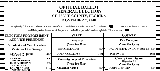
This rule covers a specific response by voters to the fact that, in many Florida counties, three letter party abbreviations were placed in a column to the right of the candidate names, while voting targets were placed in a column to the left, with the size and shape of the three letter abbreviation very similar to that of the voting target. Furthermore, the instructions on the ballot included only a filled target, not an empty one, and the example filled target was to the right of the text explaining it.
|
This design flaw was present only in the ballots used by some of the counties that used the Accu-Vote line of precinct-count optical mark-sense ballot tabulators made by Global Election Systems, among them the ballots used in Citrus (.03%), Leon (.01%) and St. Lucie (.3%) counties. Not all Global customers made this mistake! Others used various strategies to discourage this voter error, including Calhoun (0%), Hernando (.009%), Monroe (0%), Polk (.002%) and Walton (.01%) counties. The percentages listed after the county names give the fraction of voters who made this mistake, computed from the Miami Herald, Knight Ridder, USA Today data on voter errors; I have not seen sample ballots for the other Florida counties using the Accuvote system.
There is no way to anticipate, in advance, all non-prescribed markings that voters will make on ballots, and if some of these markings are specific responses to flaws in the ballot design or instructions, we cannot anticipate the markings without also anticipating the mistakes we will make in ballot design. Florida's revised election law, by prohibiting a catch-all provision, makes it very difficult to deal justly with such problems!
Michigan election law suggests an excellent solution to the problem of avoiding the catch-all provision that Florida Law and the Supreme Court decision have forbidden while not requiring anticipating every voter error. At the end of a section that otherwise leans toward a rather strict version of the machine model, we find this:
168.803 Counting and recounting of votes; rules; intent of voter.(2) If an electronic voting system requires that the elector place a mark in a predefined area on the ballot in order to cast a vote, the vote shall not be considered valid unless there is a mark within the predefined area and it is clearly evident that the intent of the voter was to cast a vote. In determining intent of the voter, the board of canvassers or election official shall compare the mark with other marks appearing on the ballot.
Michigan Election Law, Chapter 168, Section 803, Act 116 of 1954, as amended through 1997.
In contrasting this with Florida's law, we see that Michigan does not provide for nonstandard markings outside the voting target, while Florida does. On the other hand, so long as the mark is within the voting target, Michigan avoids an enumeration of marks and instead takes advantage of an important feature of a general election ballot -- the fact that the ballot generally contains multiple races, and therefore, that it will generally contain several attempts by the voter to cast votes.
|
Conclusion: We can distinguish between a deliberate but nonstandard mark and an accident by looking at how the voter marked other voting targets on the same ballot. If a similar mismarking is repeated in other races in a manner otherwise consistent with the requirement for voting, whether or not the mark is in the voting target, it is extremely likely that the mark is an expression of voter intent. |
Florida's law calls for "specific rules for each certified voting system," raising the question of how we ensure that the specific rules for one voting system are comparable to the rules for another. The proposed administrative rules that respond to this clause address all optical mark-sense voting systems as if they were the same. This is probably the correct response to a flawed law, despite the fact that different voting systems may have distinctly different responses to identical markings within similar voting targets on similarly constructed ballots.
|
Conclusion: Voters do not respond to technical details of how mark-sense scanners operate, they only respond to the instructions they are given and to the layout of the ballot. Therefore, the rules governing the interpretation of voter markings should depend only on these factors and not on the details of the scanning mechanism. |
A far greater problem with uniformity arises in the area of ballot layout and voter instructions. Florida's election law requires the following:
101.151 Specifications for ballots.--As we have seen, there was a specific design flaw in the 2000 general election ballots in several counties using the Accu-Vote line of tabulating systems. This flaw clearly traces to a "sample ... general election ballot form" that was distributed to the counties that use the Global Accu-Vote scanners. Some counties followed this sample form without modification, while others made one or another change to this form in order to reduce the likelihood of error. This ballot design error was not apparent on the two other optical mark-sense tabulating systems used in the state, and therefore, the class of voter error this design error elicited was not a problem in counties using the other systems. Sadly, in many cases, those counties made other errors.(8)(a) The Department of State shall adopt rules prescribing a uniform primary and general election ballot for each certified voting system. The rules shall incorporate the requirements set forth in this section and shall prescribe additional matters and forms that include, without limitation:
1. Clear and unambiguous ballot instructions and directions;
2. Individual race layout; and
3. Overall ballot layout.
(b) The department rules shall graphically depict a sample uniform primary and general election ballot form for each certified voting system.
Florida Election Law, Title IX, Chapter 101, Section 151, 2001
|
Conclusion: If it is unconstitutional for one ballot marking to be counted differently in two different jurisdictions, we must also ask if it is constitutional to use substantially different ballots and substantially different voting instructions in different jurisdictions, particularly when the differences are entirely avoidable and not necessary consequences of different voting systems. |
Knowing that all systems for scanning physical ballots are able to misinterpret the voter's intent, we design ballots and voting instructions that reduce the likelihood that voters will make reliably detectable marks for those candidates they wish to vote for and will assure that all other marks on their ballot are reliably ignored. One of the central problems we face today is that we have no institutions in place for determining how well we are succeeding at this!
We need to know what fraction of the voters have difficulty following the voting instructions, and how they misinterpret the instructions. We need to know the frequency of false positive and false negative marks on ballots cast by real voters, and we need to classify these marks by their causes. Aside from false positives caused by ballot defects, all of these are human factors issues! That is, they turn not on the details of the technology, but on how people react to the technology.
Recounts provide us with some help here, and the data from the 2000 general election in Florida is exceptionally useful in this regard, but that is just one sample point.
|
Conclusion: We need to routinely monitor the performance of our election systems, gathering statistics from every election in every county on the number of over and undervotes so that we can constantly monitor the quality of our ballot designs and voting instructions. At the very least, these numbers should be brought forward in the official canvass of every election. Conclusion: We need to routinely conduct hand recounts of some small but significant number of ballots in order to monitor the extent to which our ballot tabulating machines are successfully counting the marks voters are actually making on the ballots. An appropriate approach might be to require a hand count of all votes in one randomly selected race in one randomly selected precinct after every election. |
Ideally, the over and undervote numbers, along with any discrepancies found in these manual recounts, should be brought forward to a state or national agency that searches for correlations between the voting system used and the problem rate observed. The results of these studies would be of incomparable value to all of those who administer voting systems.
It is important to remember that optical-scan mark-sense ballot tabulating systems remain one of the best approaches to vote counting that we have. Unlike direct-recording electronic voting systems, scanners rely on the original paper records of voter intent as recorded by the voters themselves, and as a result, a purely software based attack on the integrity of the voting system is impossible. The voter's intent is recorded in a form that most people are comfortable interpreting, with no recourse to obscure technologies that involve chad or even more obscure technologies.
Therefore, we must find ways to improve the conduct of elections that use mark-sense tabulating systems. The improvements we need fall into two distinct categories. First, we need to improve our control over the voting systems themselves, and second, we need to improve the laws governing the use of those systems.
As has been mentioned, the current generation of mark-sense voting systems are being sold to states, counties and municipalities with no documentation of the standards the machine uses to determine what is a mark. We must require full disclosure of the following:
|
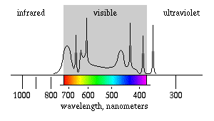
- What kind of light is the system using for mark sensing? Ideally, the vendors should be required to state far more than the wavelength of peak sensitivity or worse yet, a simple statement that the system uses some unspecified visible or infrared light. I would prefer it if the vendors gave the spectral response of the system as a graph that was clearly labeled with the visible color spectrum for comparison purposes, as illustrated in Figure 16. The spectrum in the figure is typical of the spectra expected from scanners that use fluorescent light sources. Note that this is not simply a graph of the output spectrum of the light source in the scanner, nor is it simply a graph of the spectral sensitivity of the photosensors, but rather, it is a graph of the product of these two!
- What criteria does the ballot tabulator use to distinguish between acceptable marks and unacceptable marks? This involves answers to a number of subsidiary questions such as: Is the entire voting target inspected on each scan, or just a portion, as in a typical scanner based on discrete sensors? Is the area scanned larger than the target printed on the ballot? Is the mark recognition system more sensitive to marks in one region of the voting target or in one orientation than in another region or orientation?
- What kinds of marks are reliably detectable by this ballot tabulator, what kinds of marks are reliably ignored, and what kinds of marks are marginal. Ideally, the documentation for the scanner should include samples of each class of mark. These serve to illustrate, by example, the criteria the system uses, and they also serve to illustrate how close to marginal the prescribed mark is and how reliably the system is in ignoring marks such as erasures and hesitation marks.
The fact that mark-sense ballot tabulating equipment occasionally miscounts votes can be dealt with in several ways. In Florida, for example, when there is a recount, all overvoted and undervoted ballots are subject to hand examination. Michigan's law is closer to the machine model, but it too allows a hand recount and it too allows the examiners during a recount to interpret as votes at least some marks that the machine may have ignored.
In order to ensure an accurate count, we need to regularly audit our voting systems, we need to ensure that marginal marks are judged by humans. In order to accomplish these goals, we must require the following:
- Whenever practical, we must return overvoted and blank ballots to the voter for correction. This will allow the voter to correct overvotes, both those that were caused by false positives and those resulting from ineffective attempts to correct errors. This is easily done with precinct-count voting systems, but it is not possible with mail-in absentee ballots.
- When it is impractical to return an overvoted or blank ballot to the voter for correction, or when a voter refuses the opportunity to change a ballot that was returned by a precinct count scanner, this ballot should be subject to hand examination. This requires that central-count equipment sort out all overvoted and blank ballots, and this requires that such ballots found at polling places be set aside for inspection. The methods of ballot enhancement or duplication used for absentee ballots that have been damaged in the mail should apply to all such ballots.
Assuming that we have appropriately uniform rules for hand-interpretation of marks on ballots, and that these rules give the voter broad latitude for expressing his or her choice on the ballot, the above rules give central-count voters almost as much protection as they give voters who use precinct-count systems.
- To ensure that there are always a number of election workers who have had experience hand counting ballots, and to ensure that the counts reported by our ballot tabulating equipment are accurate reflections of the legal standards for what constitutes a vote, we should require routine hand counting of a small fraction of the ballots in every election. For example, we could require a hand recount of one randomly selected race in one randomly selected precinct after every election, with all discrepancies reported to the state. If the state finds that some voting system has a uniformly higher discrepancy rate than others, it should trigger reexamination and possible discontinuation of the use of that system!
- To ensure that all ballots are accounted for, and in order to monitor the frequency of voter difficulty, we should require that the number of spoiled ballots be carried forward through the canvassing process in every election. Ideally, the total number of votes for each candidate in a race, plus the number of overvotes and undervotes in that race, plus the number of spoiled ballots, plus the number of challenged ballots, plus the number of unreturned absentee ballots ought to equal the number of ballots given to voters. This is a strong protection against many forms of election fraud. In addition, the number of spoiled ballots is a measure of the frequency with which voters had difficulty and therefore a measure of the likelihood that other voters may have had problems that went undetected.
Recounts are expensive, and therefore, no election administrator wants to encourage them. In order to reduce the frequency of recounts, some states require those requesting a recount to post bond, and many states forbid a recount unless the election is sufficiently close. The problem is, we must permit and in fact encourage recounts if it is even remotely possible that the miscounted votes in a race could change the outcome.
- It is appropriate to allow recount requests when the election is close, for example, if the margin of victory of the apparent winner is smaller than some set percentage. Given that it is common for recounts to come within 1 vote in 5000 of the first count in the absence of any accounting or procedural errors, allowing recounts when there is a margin of under 1 percent seems generous.
- There are some benefits that go to participants in an election even if they lose. For example, if a party gains 5 percent of the vote for any statewide office, some states grant that party special status -- automatic placement on the ballot in the next election, for example. Therefore, we need to allow recounts if a candidate comes within range of such a threshold. For example, we could allow a recount if a candidate comes within 1 percent of the number of votes required to achieve any statutory benefit from the election.
- We need some way to allow recounts if there is evidence that there were problems with the election! As many as 10% of the voters in some Florida counties made errors on their ballots in the 2000 general election. The count of spoiled ballots plus ballots that required enhancement or duplication provides a measure of the frequency with which voters had difficulty. If this number is high, there is a high likelihood that other voter difficulties went undetected. Therefore, if this number exceeds some threshold, no matter how close the election was, we should allow a recount. For example, we may allow a recount when the number of spoiled ballots plus ballots that required enhancement or duplication exceeds 1% of the total.
One purpose of a recount is to assure that an eccentric count of marginal votes is not a significant component of the outcome of the election. To ensure this, we must demand the following:
- The vote tabulating machines used in a recount should be tested and recalibrated prior to the recount in order to ensure that their sensing thresholds are correct. In addition, if possible, the tabulating machines used for the recount should not be the same machines used in the original count; this ensures that the ballots will be seen by different scanners and it maximizes the likelihood that marginal marks will be interpreted differently on the recount.
- Given that overvotes have been dealt with prior to the first count, therefore correcting most false positives, it is appropriate to hand inspect all ballots that show an undervote in the race being recounted in order to catch and correct most false negatives.
- If the number of spoiled ballots plus the number of ballots requiring enhancement or duplication exceeds the margin of victory of the apparent winner, it is highly likely that other ballots contain errors that did not lead to over or undervotes; in this case, it seems appropriate and perhaps necessary to allow a hand recount of all ballots cast in the race.
Whenever a ballot is examined by hand, whether to deal with a blank or overvoted ballot that the voter has not corrected during the first count, during a routine hand recount conducted for auditing purposes, or during a recount conducted at the request of a party to the election, the same criteria should apply to interpreting voter marks.
- The class of acceptable marks must include all reliably acceptable marks that are not the result of errors in ballot printing, erasures or other obvious corrections, or stray marks.
- The class of acceptable marks must include those marginal and reliably ignored marks that appear to be deliberately made as indications of voter intent. A mark should be accepted as an indication of voter intent when similar marks have been used in multiple contests on the ballot and where most such marks conform to the other rules of the election, for example, voting for no more than one in most vote-for-one races.
- Attempts at erasures, striking out an otherwise acceptable mark, and written notations indicating errors should be accepted at face value, despite rules forbidding erasure or correction.
- Defects in the ballot and stray marks that do not meet the criteria for acceptable marks should be ignored.
First posted on the web, February 2002; this document was originally prepared in conjunction with the author's work on the 2001 Iowa Ad Hoc Election Reform Task Force, convened by Iowa Secretary of State Chet Culver to examine the need for Iowa to respond to the problems exposed by the general election of 2000.