Braille Printer PhotosA project from 1980
Part of
the Braille Printer Web Pages
These photos date from when I worked at the University of Illinois School of Basic Medical Sciences at Urbana |
Braille Printer PhotosA project from 1980
Part of
the Braille Printer Web Pages
These photos date from when I worked at the University of Illinois School of Basic Medical Sciences at Urbana |
I took these photos in early 1980 during the assembly of the Braille printer. I scanned them in 2022 from 8 inch wide prints that had been stored in a manilla envelope for over 40 years.
Note that I took the photos during printer assembly, and none of them show the printer in its final working state. Photos showing the wiring include a small number of wiring errors that we fixed after the photos were taken, and other wiring and parts were not yet installed when I took the photos. None of the photos include the carriage motor, and none include the final platten assembly with its brass platten and toggle-jointed paper holddowns.
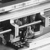
Numbers (such as 3.1.7.1) given with each figure reference the parts list making up section 3 of the text.
|
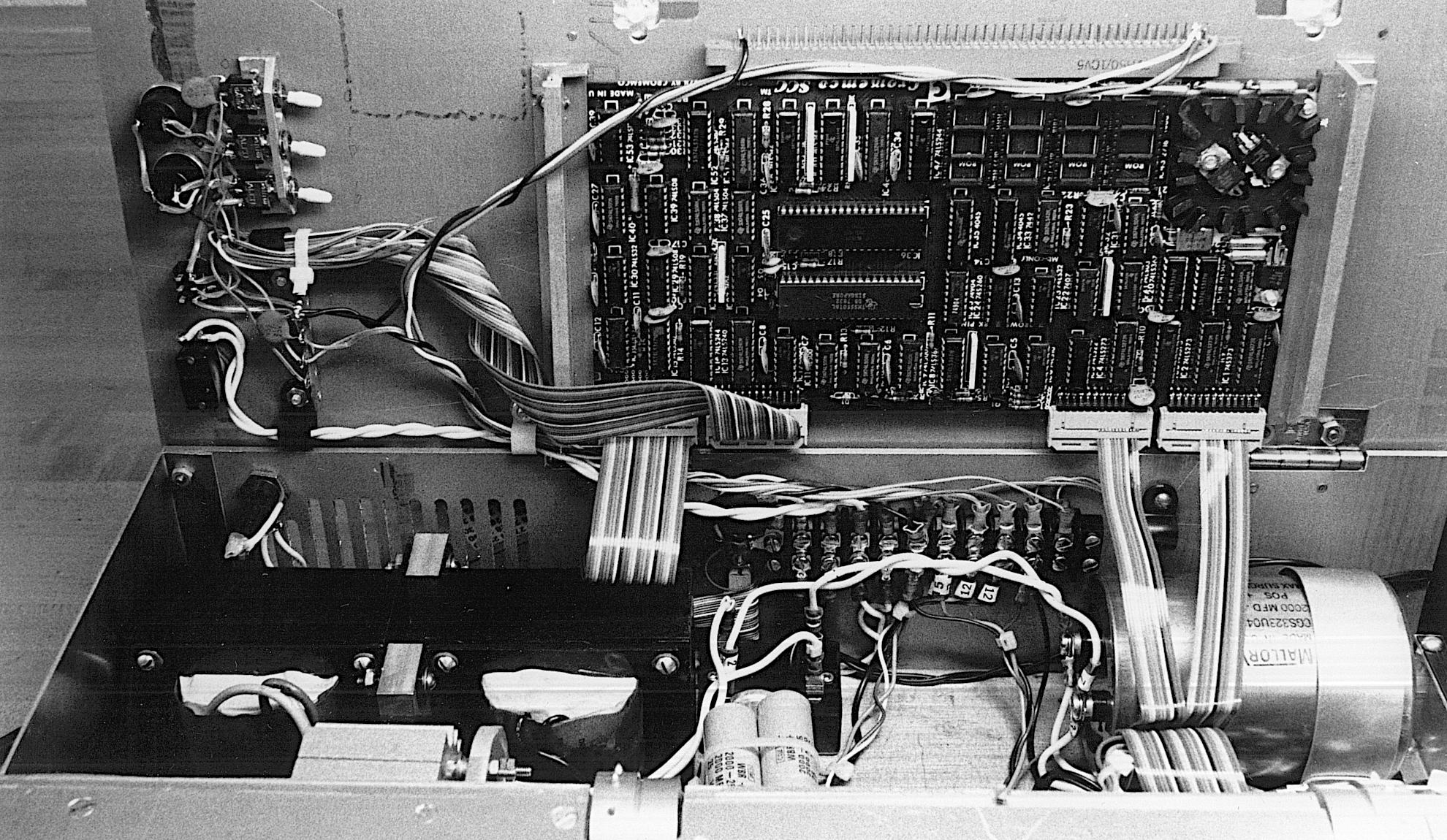
The empty space in the center left will be largely filled by the carriage
motor, and the empty space at the lower right is where the circuit card
will go.
|
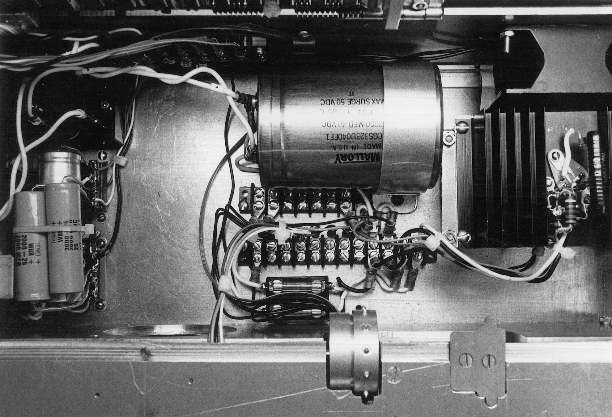
The two big transformers on top are wired in parallel to provide the 24 volts at fairly high current needed by the carriage motor. The two smaller transformers provide logic power and the +/- 12V power needed by the single card computer.
At the bottom of the photo, in front of the motor mounting plate, you can
see the microswitch used to sense the carriage home position and the
loudspeaker used to indicate error conditions. These both sit under where the
paper advance assembly will go.
|
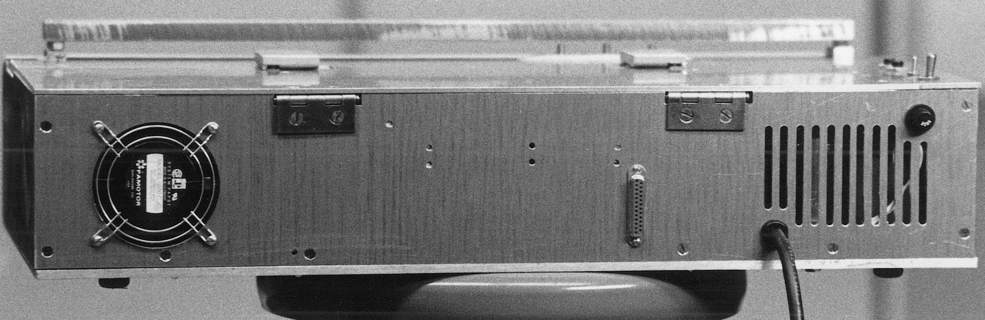
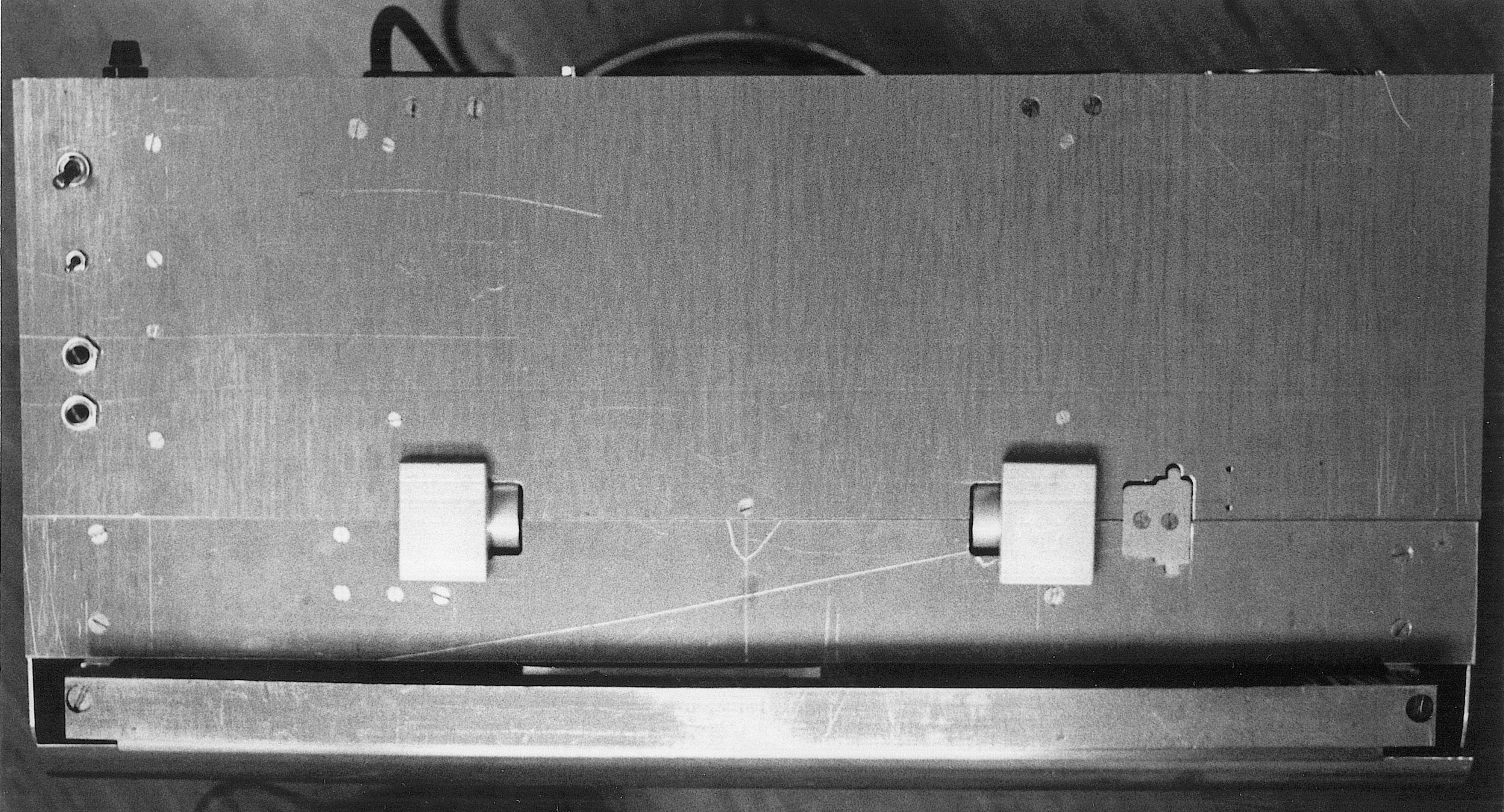
The paper hold downs, visible from the rear on top of the printer did not work,
so they were redesigned. The problem was that the tension on the paper
required to pull embossed braille bumps out of the dies on the platten was
enough to lift the hinged lids over the sprocket teeth.
|
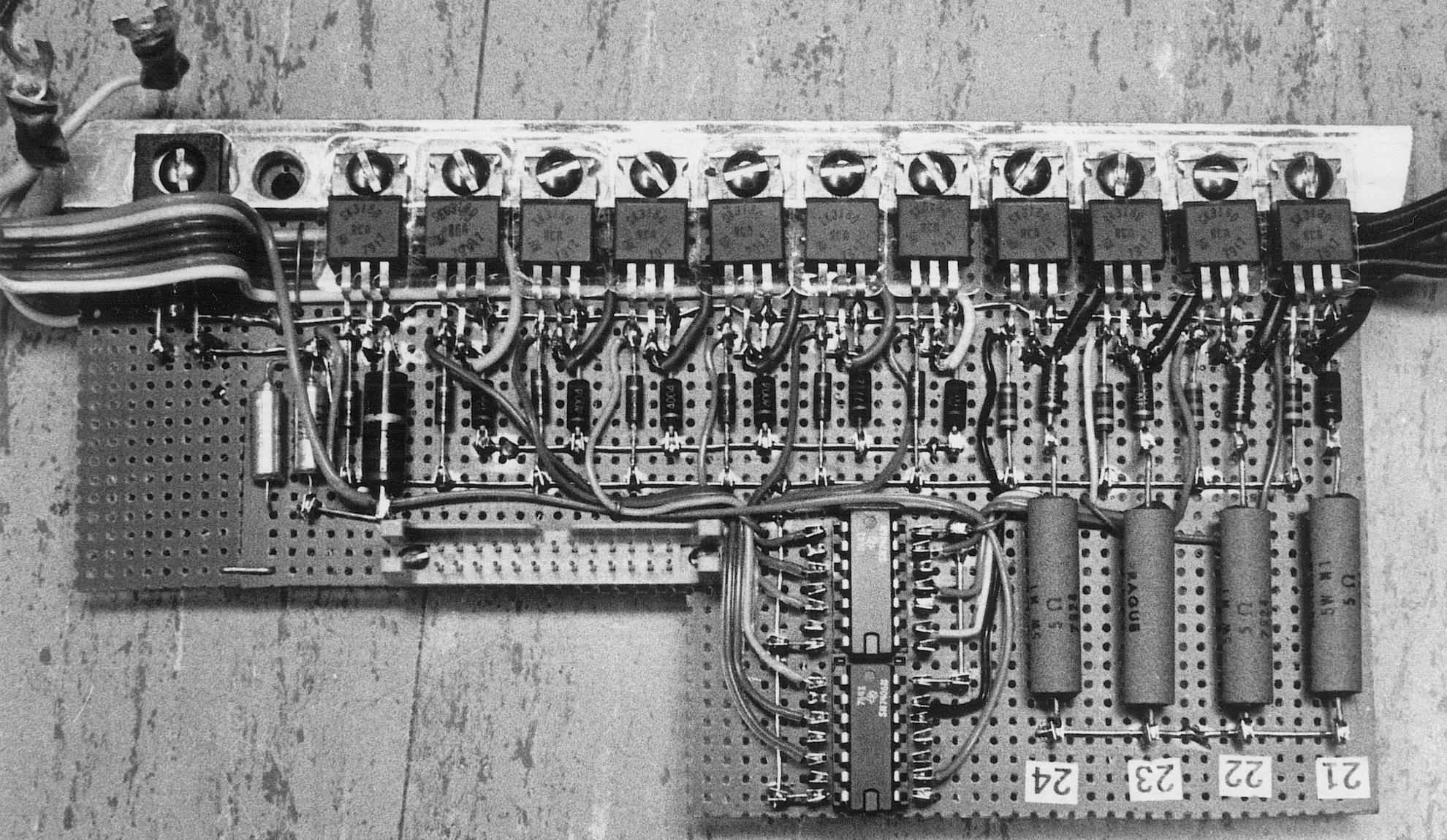
The rightmost transistors switch the power to the carriage motor windings. These high-current windings need fast rise time, ensured by the current limiters, and fast fall time, helped along by the 5-ohm power resistors on this board.
The notch in this circuit card clears the paper advance sprocket.
|
The photo also shows that the ground for the higher power circuits
(solenoids and motors) has been carefully separated from the logic ground.
These grounds were only connected at one point, on terminal strip I.
|
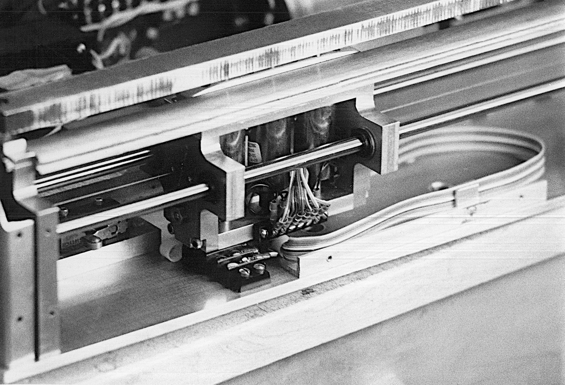
Barrier strip K under the carriage is linked by the loop of ribbon cable
to barrier strip L on the side of the carriage. At the left end of its travel,
the carriage closes the microswitch visible to the left.
|
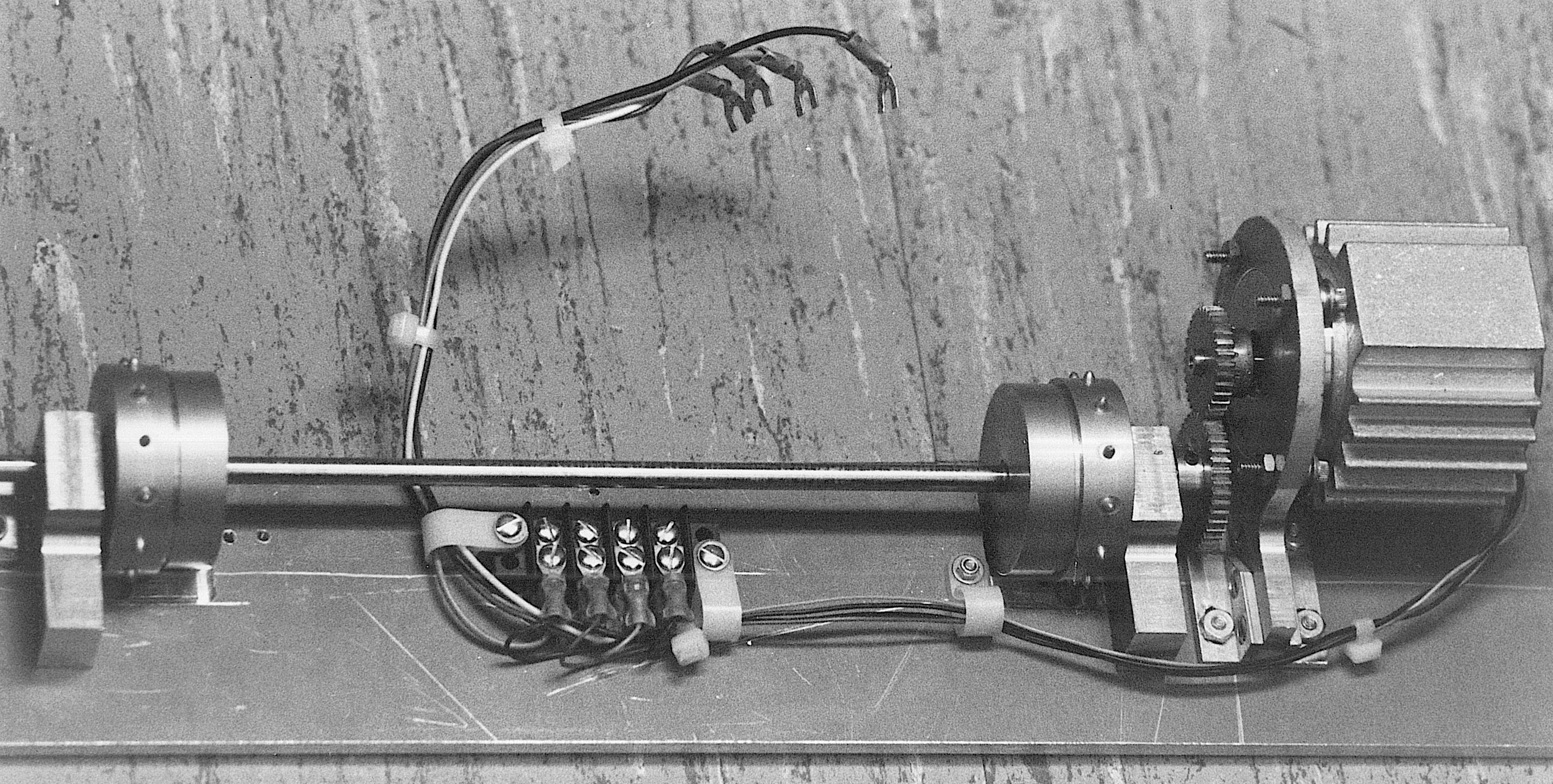
Barrier strip J is close enough to the motor to be within easy reach of the
pigtail leads of the motor wires and it supports wires just long enough to reach
barrier strip D by the circuit card.
|
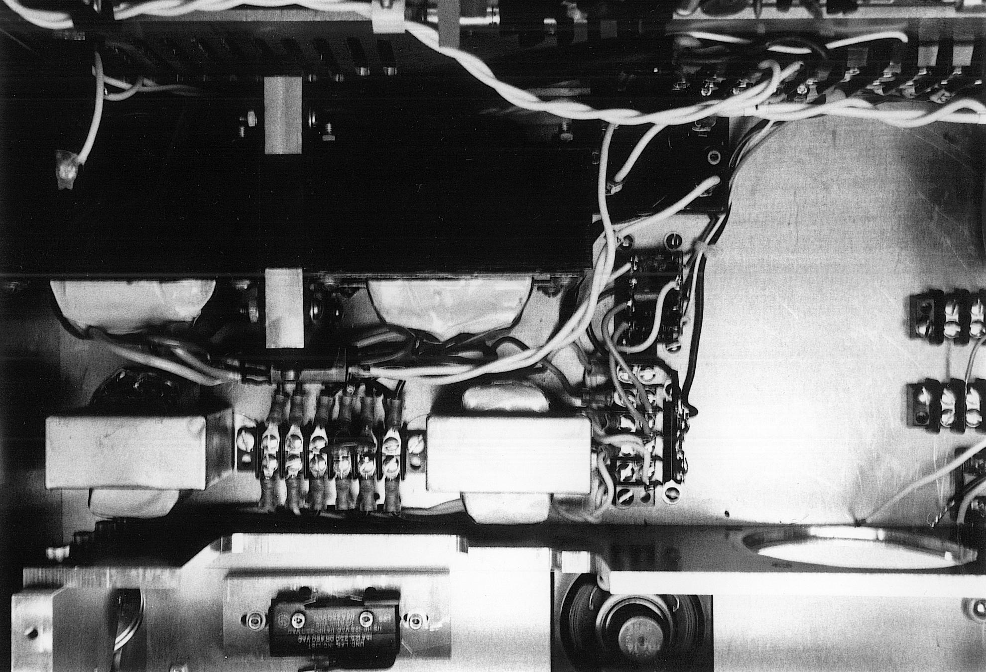
The 3 internal control switches are for options that the user is not
expected to set, while the external switches and buttons are for user
controls.
|
The controls to the left of the paper path include a big on-off switch, a small operating mode switch and two push buttons, one for linefeed (single line advance) and one for form feed (full page advance).
Some of those who looked at our prototype wondered why we didn't include any status LEDs. Visual indicators are of little use for a blind user, which is why we put a loudspeaker in the printer. We found ways to use the speaker to indicate a number of error conditions, including a horrible noise to mean "turn me off now" — on hearing this, nobody we tried it on needed to be told what to do.
The paper advance mechanism can be reconfigured for narrow (letter size) paper or wide (computer printer size) paper. Reconfiguration requires partial dissassembly of the paper advance mechanism, so it is not very convenient.
The photo shows the early hinged hold-downs for the paper over the sprockets.
As already noted, this design did not work well and was replaced.