Braille Printer Design MethodologyRecalled 42 years later: how we designed it
Part of
the Braille Printer Web Pages
|
Braille Printer Design MethodologyRecalled 42 years later: how we designed it
Part of
the Braille Printer Web Pages
|
The initial point in designing this Braille printer, or Braille embossing machine, was the realization that, in any dot-matrix printer or Braille embosser, the mechanisms that print or emboss each dot in a column need not be arranged in a column. Instead, they may be on a diagonal, so long as the control system is flexible enough to take this diagonal into account.
In the case of a Braille printer, this allows three large-diameter solenoids arranged in a very shallow diagonal on the printing carriage to do the embossing.
The printer control system needed to support our idea requires that each line of Braille be decomposed into dots before that line is printed and then, as the carriage scans across the line, the individual dots are embossed, with dots in different characters being embossed simultaneously. This effectively requires a computer inside the printer, and single board computers were becoming widely available.
Having hit on this idea, the next step was to measure the force required to emboss a Braille dot. The heavy paper used for Braille turns out to be quite strong. Even common notebook paper takes a significant fraction of a pound to emboss.
Having measured the force required to emboss a dot, we searched catalogs of push-solenoids to find one able to exert that much force, including taking into account use of a return spring to pull the punch out of the embossed dimple. We immediately decided to grind the embossing punch directly on the end of the solenoid's push rod.
The design of the carriage followed largely from the dimensions and mounting provisions of the embossing solenoids. To support the carriage, we looked at various linear bearings and decided on recirculating ball bushings sliding on round ways because these offered very low friction, good load capaicty and decent rigidity.
With the carriage design complete, we could estimate the weight of the carriage in order to figure out the forces needed to move it. We assumed it came to a complete stop to emboss each dot, so our carriage drive system had to accelerate and decelerate the carriage repeatedly as the various dots on a line were embossed.
The printing speed is a critical feature of any printer, so we estimated the time needed to emboss each dot and then set the force that the drive could apply to the carriage to make the time to move from one Braille dot to the next comparable to the time we estimated it would take to emboss a dot.
Knowing the force required, we opted to use a tendon drive, that is, a flexible stainless steel cable wrapped around pullies at each end of the carriage and around a drum on the shaft of the carriage drive motor.
We found that model aircraft control line was widely available in a variety of tensile strengths, so we selected a line with a rated tensile strength roughly twice the force we needed to move the carriage and measured its flexibility. All pullies and the winding drum we used had to involve purely elastic bending of the cable, so we measured the maximum radius that left a permanent bend in the wire and then tripled that to set the working radius.
Knowing the drum diameter and the force we wanted to apply gave us the torque the motor needed to apply. We decided to use a stepping motor, so the search was on for a motor that could supply the necessary force and had a step size that divided evenly into the spacing between Braille dots. This was, to some extent, an iterative process, because getting the spacing right required changes to the drum diameter.
We decided to use sprocket-feed paper, so the first step in the paper transport design was to find a sprocket that matched the hole spacing, with a large enough diameter to engage enough sprocket teeth to pull the paper reliably. Such sprockets, fortunately, were available on the market so we did not have to try to make them.
Again, we decided to use a stepping motor, so we looked for a motor with a step size that, at the sprocket diameter, divided evenly into the vertical spacing between Braille dots, and one that offered enough torque to reliably lift the weight of paper feeding from a fanfold paper box on the floor.
The motors big enough to meet this demand were larger in diameter than the sprocket, so we decided to gear the motor to the shaft. This allowed us to use gearing to adjust the step size.
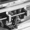
We did not initially put much thought into a hold-down mechanism to keep the paper on the sprocket teeth. Our initial design for the hold-downs is shown in the printer photos. This did not work well. The drawings show the hold downs we eventually hit on, as well as the addition of rubber tires (common rubber bands) to the sprockets. (In retrospect, rubber bands were probably a bad choice, they degrade fairly quickly and would have been a nuisance to replace.)
The final afterthought we added to the paper transport mechanism was a pair of paper guides on the front side of the printer. Without these guides, the paper occasionally skewed from side to side as one or the other sprocket began to pull loose or as slight friction with the carriage dislodged it. The guides were trivial, just cap-screws countersunk slightly into the top of the bar that guides the paper into the printer, so that the cylindrical body of the screw head guided the paper. The small countersink was needed to prevent there being a place for the edge of the paper to catch under the slightly rounded underside of the screw head.
With the solenoids, carriage motor and paper advance motor all selected, we could determine the power requirements of the system. We used solenoids and designed for 24 V DC intermittent operation, and a paper-advance motor designed for holding its position at 24 V DC.
Stepping motor performance is significantly improved when the motor is driven with a high voltage current-limited supply. This is because higher voltage leads to faster current rise in the motor windings when they are switched. Taking this into account, we opted for a carriage positioning motor with low resistance windings powered at 24 V DC, with series current limiters for the windings.
The transformers big enough to supply the total current required, at 24 V, were too big to fit comfortably in the case, assuming that the height of the carriage would determine the case thickness. So, we used two transformers wired in parallel. We also added two smaller transformers to provide logic power to the single card computer and the control circuitry.
The data sheets for several of the large motors we looked at explained how to use a large power resistor to limit the motor current, but when we priced the resistors we needed (50 watts!) we found that they were quite expensive. In contrast, transistors able to handle that power level, along with the necessary heat sink and other parts were surprisingly inexpensive.
So, we opted to build transistorized current limiters, with heat sinks mounted just upstream of the exhaust fan that ventilated the case. Even without the need for current limiters, we knew that a fan would be needed. With over 100 watts being dissapated by the current limiters, we had to do some work to compute the airflow required to keep them appropriately cool.
During much of our initial development, we used a rubber mat glued to the underside of the platten support bar as a platten for embossing Braille bumps. During this development period, the tips of the solenoid plungers were turned to conical points. The rubber was soft enough that this produced a marginally acceptable result when embossing cheap line-printer paper, and it allowed us to do quite a bit of debugging before we worried about producing a high-quality platten with drilled holes for embossing.
Braille slates used for hand-embossing Braille are usually made of work-hardened (cold rolled) alumiminum plate. We opted to make our final platten out of brass. Because any slight mis-machining of the carriage advance winding drum would lead to a change in the spacing of the Braille cells, we mounted the brass platten on the underside of the support bar, and then used the solenoids as center punches to mark where the brass platten should be drilled to make the final embossing dies.
The temporary conical points on the solenoid plungers made good center punches, but after drilling the platten, we also removed the plungers from the solenoids and turned new rounded points on them somewhat smaller in diameter than the holes in the platten. We did not have to completely dissassemble the carriage, but merely removed the bottom plate so the solenoid plungers could be dropped out through the holes in the bottom plate. Those holes were there to help in installing the carriage haulage cable, but they were deliberately big enough and positioned to pass the solenoid plungers.
The clatter of the solenoid plungers against the platten was loud when the printer was in operation, and part of this was because the entire platten resonated. To damp this resonance, we milled away the brass on the back of the brass platten behind the embossing dies in order to put a rubber mat there. This significantly lowered the noise level. We also put a rubber mat in the bottom well of the carriage where the tail ends of the solenoid plungers rested when they were idle.