Embossing mechanism
  

Braille Printer Drawings

A project from 1980

Part of the Braille Printer Web Pages
by Douglas W. Jones
and Andrew Appel
THE UNIVERSITY OF IOWA Department of Computer Science and
Princeton University Department of Computer Science

This dates from when we worked at the University of Illinois School of Basic Medical Sciences in Urbana

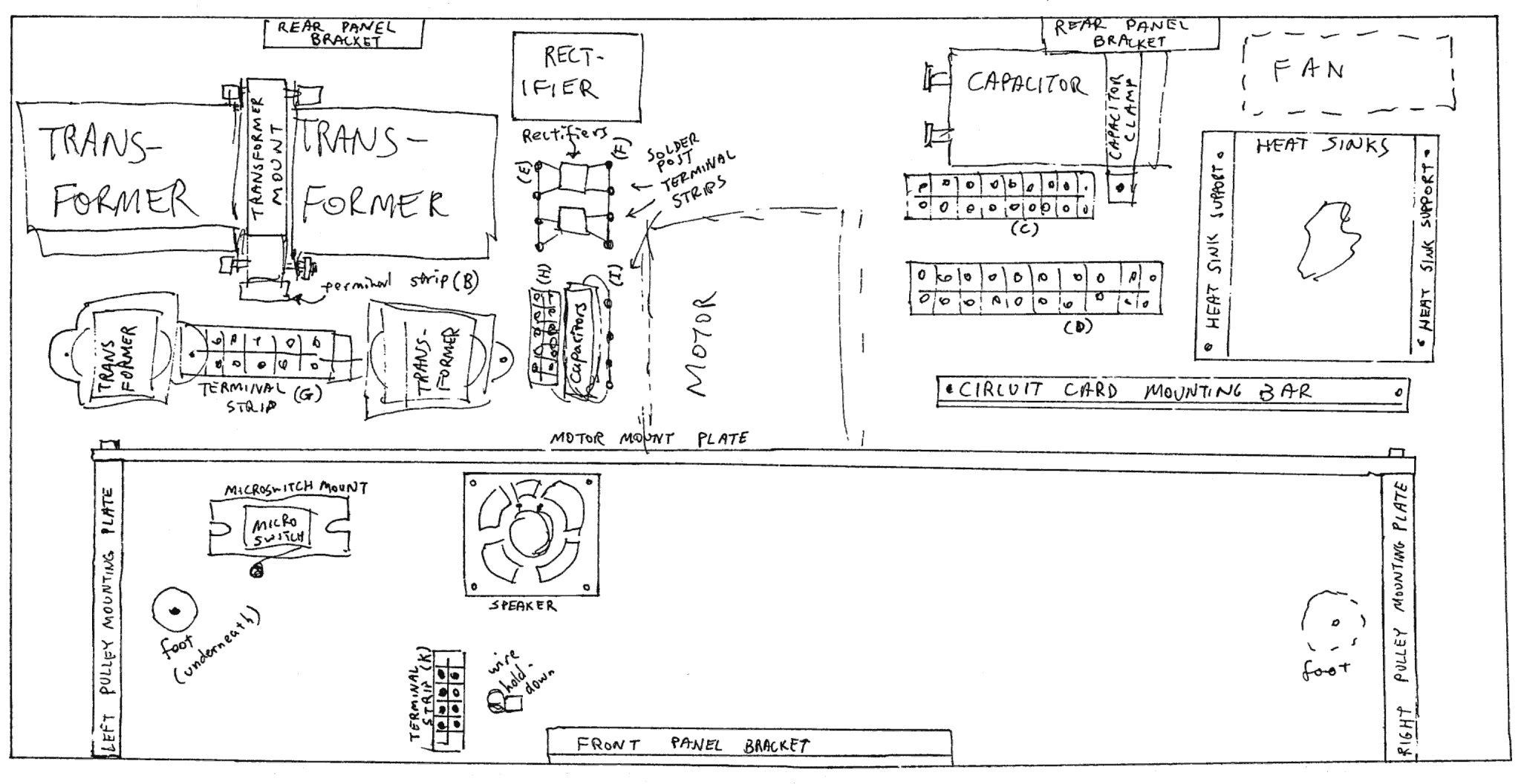
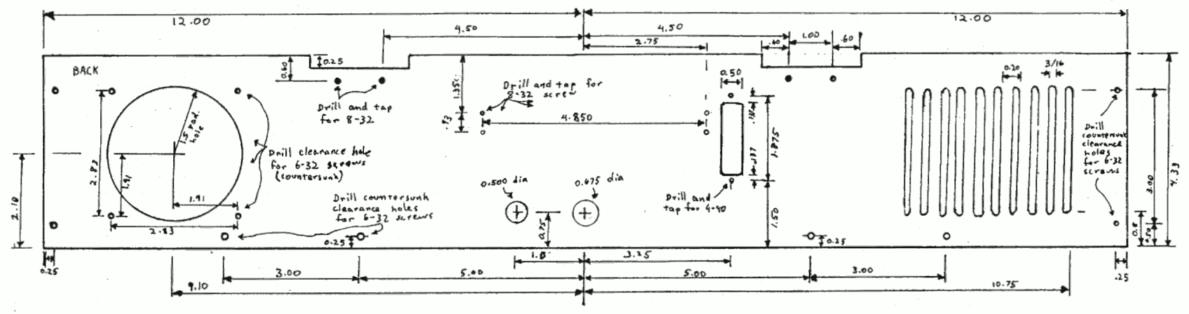
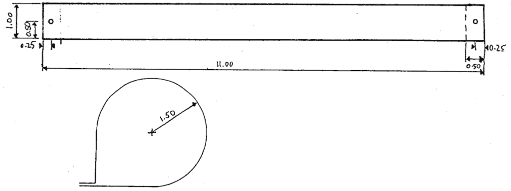
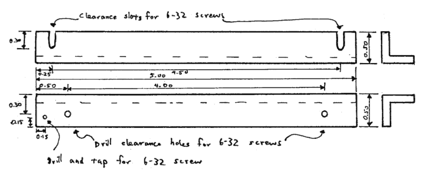
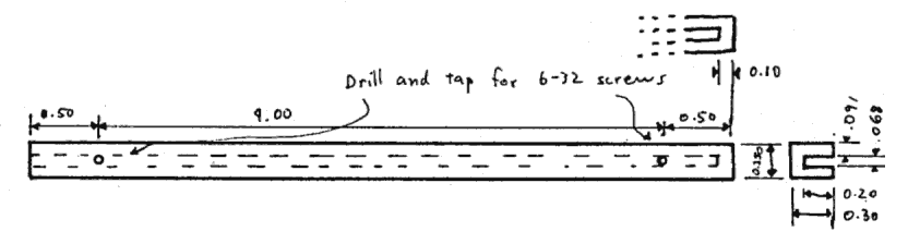
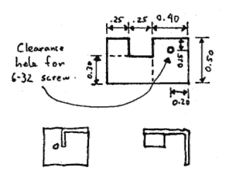
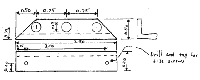
Dimensions are expressed as:
0.0are ±0.05
0.00are ±0.005
0.000are ±0.0005
All dimensions are in inches.

Most of the parts are aluminum, even those specified as brass, except:

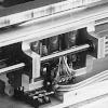
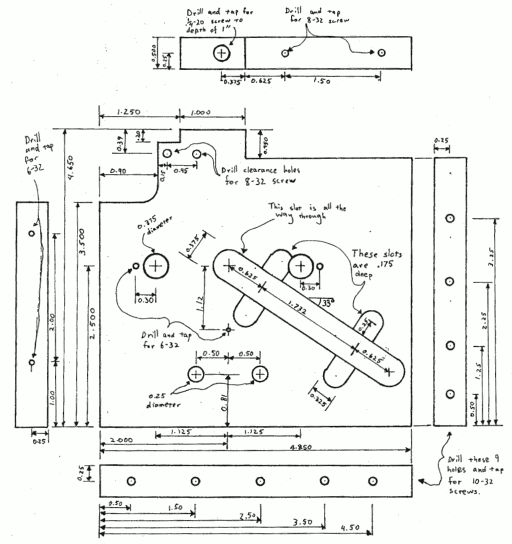
Numbers (such as 3.1.7.1) given with each figure caption reference the parts list making up section 3 of the text.

Base Plate Layout (3.1)
link to drawing showing parts layout

Baseplate (3.1.1)
Thickness 1/4 inch
link to drawing, 12 by 24 by 1/4 in. plate with many holes

Rear Cabinet Layout (3.1.2.1)
link to drawing showing parts layout

Rear Cabinet Panel (3.1.2.1)
Thickness: 1/8 inch
link to drawing, 24 by 4.33 by 1/8 in. plate with many holes

Rear Panel Bracket (3.1.2.7)
(2 required)
link to drawing, 1/2 inch angle 6 inches long with 4 holes

Heat Sink Support (3.1.3.2)
(2 required)
Material: 1/16 Aluminum
Cut, drilled, then bent into shape
link to drawing, 3 by 3 in. sheet, with 4 holes, bent in U shape

Transformer Mount (3.1.4.1)
link to drawing, 3 by 3 by 1/2 in block with 8 holes.

Capacitor Clamp (3.1.6)
Thickness: 1/16
link to drawing, 11 by 1 in sheet with 2 holes, bent in a ring

Circuit Card Assembly (3.1.7) Transistor must be in thermal but not electrical contact with mounting bar.
link to drawing showing mounting of transistors and circuit card

Circuit Card Mounting Bar (3.1.7.1)
link to drawing, 1/2 inch angle 7 inches long with 15 holes

Circuit Card (3.1.7.2)
Material: Perforated fiberglass board
link to drawing, 3.5 by 7 inch perfboard with a notch

Microswitch Mount (3.1.12.1)
(thickness 0.500)
link to drawing, 3 by 1.25 by .5 block with 4 deep notches

Carriage Installation (3.1.12.1)
link to diagram showing relations of carriage drive parts
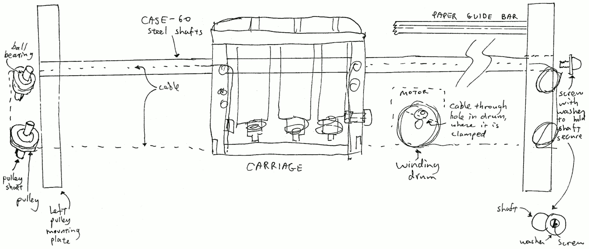
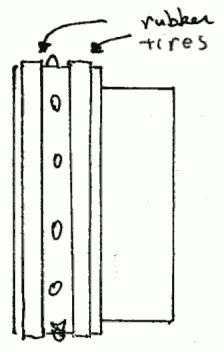
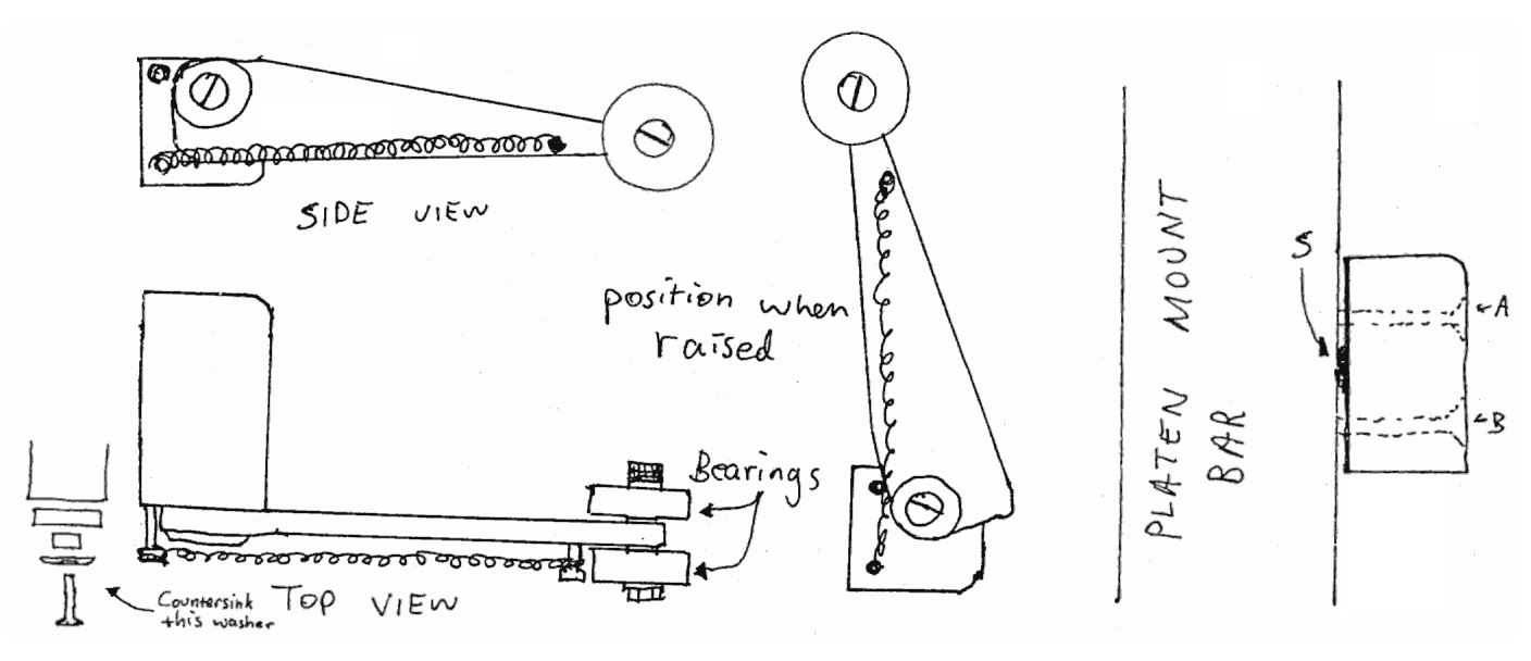
To install the carriage cable:
1) Cut a 6-foot length of cable.
2) Feed it through the hole in the winding drum and tighten the clamp screw in the winding drum leaving an approximately equal length of cable on either side.
3) Wind each end around the drum 3 times one end on each side of the clamped cable.
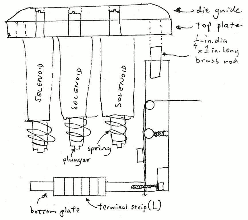
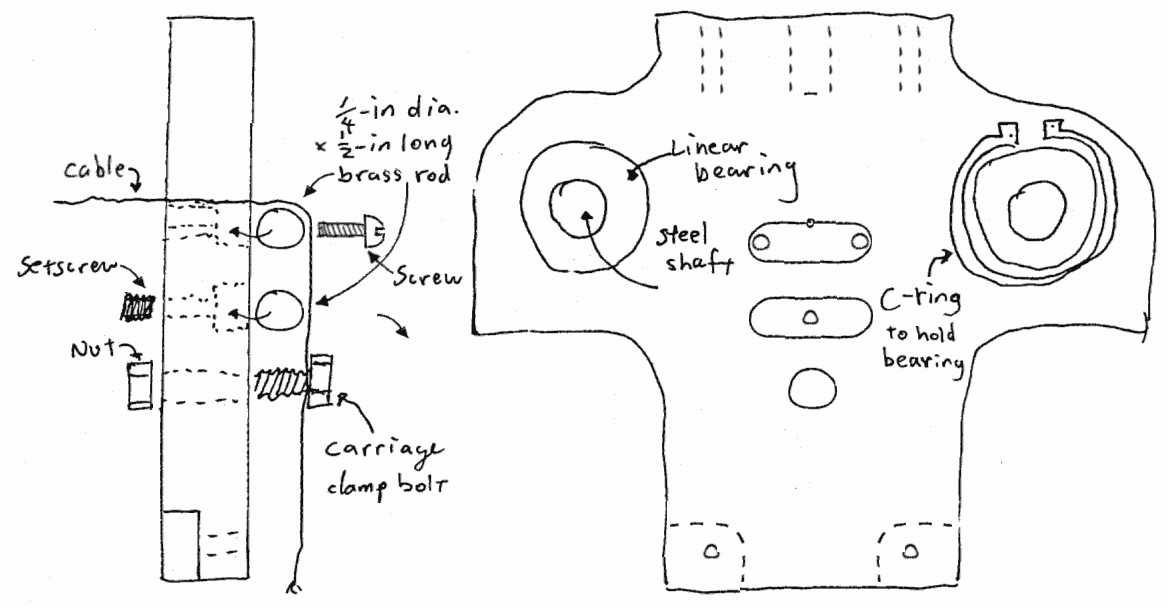
4) Feed the cable around the pulleys on each end plate,
  a) through the small hole in each carriage end plate,
  b) down around the short brass rod in the slot in the end plate,
  c) down through the carriage clamp bolt,
  d) down through the holes in the ends of the carriage bottom plate,
  e) and down through the large holes in the base plate.
5) Tighten one clamp bolt (either one).
6) Attach a 20-pound weight to the unclamped end of the cable.
7) Tighten the clamp bolt above the weight.
8) Cut off the excess cable at both ends, even with the bottom of the carriage.

Paper Advance Mechanism (3.2.1)
Assembled, rear view
link to drawing of assembled paper advance mechanism

Paper Advance Plate (3.2.1.1)
Thickness: 1/4 inch
link to drawing, 24 by 2.425 by 1/4 in, 18 holes, 3 big notches

Paper Advance Motor Assembly (3.2.1.2)
Note: Motor shown installed from wrong side.
link to sketch showing how motor is attached to mounting plate drawing with dimensions

Paper Advance Motor Mount Plate (3.2.1.2.1)
Thickness: 1/4 inch
link to drawing, P-shaped 2.75 in. diameter with 2.5 by 3/4 stem

Paper Advance Motor Mount Angles (3.2.1.2.2)
link to drawing, 1/2 in. angle 1.25 and 1.75 in. long with holes link to drawing, 2 by 1.125 by 1/2 in block, 3 holes, a notch

Paper Advance Shaft Support (3.2.1.3)
(2 required)
Press fit sintered bronze bearing (3.2.1.4.4), into each shaft support, ream bearing if necessary to allow 1/4" shaft to spin freely.
drawing with dimensions

Paper Advance Shaft Sprocket (3.2.1.4.1)
(2 required)
1/8" wide rubber bands work well as tires on each side of each sprocket.
link to sketch showing how to use rubber bands as sprocket tires

Motor Mount Plate (3.2.2.1)
link to drawing, 22 by 3.75 by 1/4 in. plate, 14 holes 2 notches

Winding Drum (3.2.2.3)
Material: Brass
Note: To drill the nearly tangent hole in the rim of the drum, first nick the drum with a small diameter end mill coming in perpendicular to the axis of the hole to make a place to start drilling. Drill this hole before milling in from the side for the 6/32 clamp screw.
link to drawing, 1.62 in. dia, 0.6 in thick, 6 holes

Right Pulley Mounting Plate (3.2.3.1)
Note: Left Pulley Mounting Plate is the same except
the 0.175 deep slots are on the other side.
link to drawing, 4.65 by 4.85 by 1/2 in. with holes, slots etc.

Pulley Rim (3.2.3.2.2) (4 required)
Material: brass
Note: gentle press fit onto ball bearings 3.2.3.2.1
link to drawing, 1.4 in. diameter, 0.25 in. thick with groove

Pulley Shaft (3.2.3.2.3)
(4 required)
Material: brass
Note: This is 1/4" diameter, nominal. Actually, it should be of the right diameter to be a press fit with the ball bearings 3.2.3.2.1 and an easy fit in the slots in the end plates 3.2.3.1
link to drawing, 0.25 in. diameter by 0.8 in. long shaft

Platten Mount Bar (3.2.4.1)
Material: 1" × 0.5" aluminum bar
Note: Round ends and upper corners so nothing on top is sharp.
link to drawing, 24 by 1 by 1/2 in. bar with 19 holes

Platten (3.2.4.2)
Material: Brass
link to drawing, 12.5 by 1 by 1/8 in. plate, 7 holes, 40 Braille cell dies

Paper Hold Down Assembly (3.2.4.3)
Material: Brass
Note: When mounting each hold down to the back of the platten mounting bar, a small blob of solder or anything similar at point S allows either screw A or B to be tightened to finely adjust angle of block and thus to adjust position of the bearings at the end of the hold-down strut.
link to sketch showing assembly of toggle mechanism and rollers

Paper Hold Down Mounting Block (3.2.4.3.1)
(2 required, one a mirror image of the other)
link to drawing, 1 by 0.6 by 0.6 in. block with 5 holes

Paper Hold Down Strut (3.2.4.3.2)
(2 required)
Material: 1/8" Brass
link to drawing, 2.7 by 0.5 by 1/8 bar, tapered, with 3 holes

Paper Hold Down Pivot Pin (3.2.4.3.3)
(2 required)
The diameter of this pin should be so as to make an extremely precise sliding fit into the hole in the strut, and the length should be just a bit more than the thickness of the strut.
link to drawing, 0.2 in. diameter by 1/8 in. thick with 1 hole

Paper Guide Bar (3.2.5)
The heads of the cap screws in the front edge of this bar should protrude enough to serve as paper guides.
There are 3 holes, but only two screws should be used, the holes used depending on the paper width.
link to drawing, 21 by 3/4 by 3/8 in. bar with 7 holes

Carriage Assembly (3.2.7)
link to sketch showing solenoids mounted in carriage
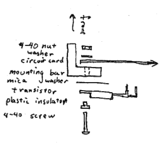
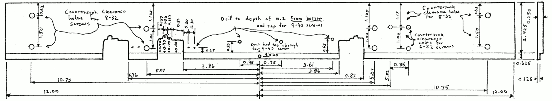
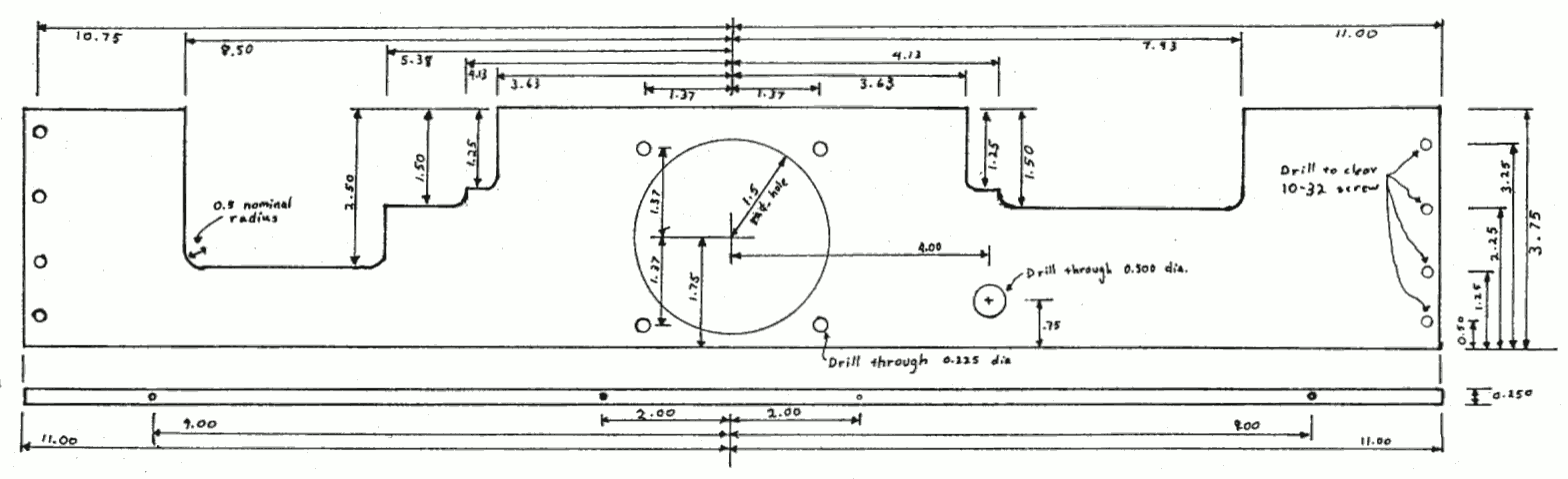
Make 2 1.00 × 0.250 dia pins (dia +000,-0.001) to hold carriage top plate to end plates.
Fix top plate to end plate with 4 8/32 × 3/4 cap screws, slots with pins in end plates face each other.
Loosely mount clamp bolts in 1/4 dia holes in end plates, bolt head inside, nut outside.
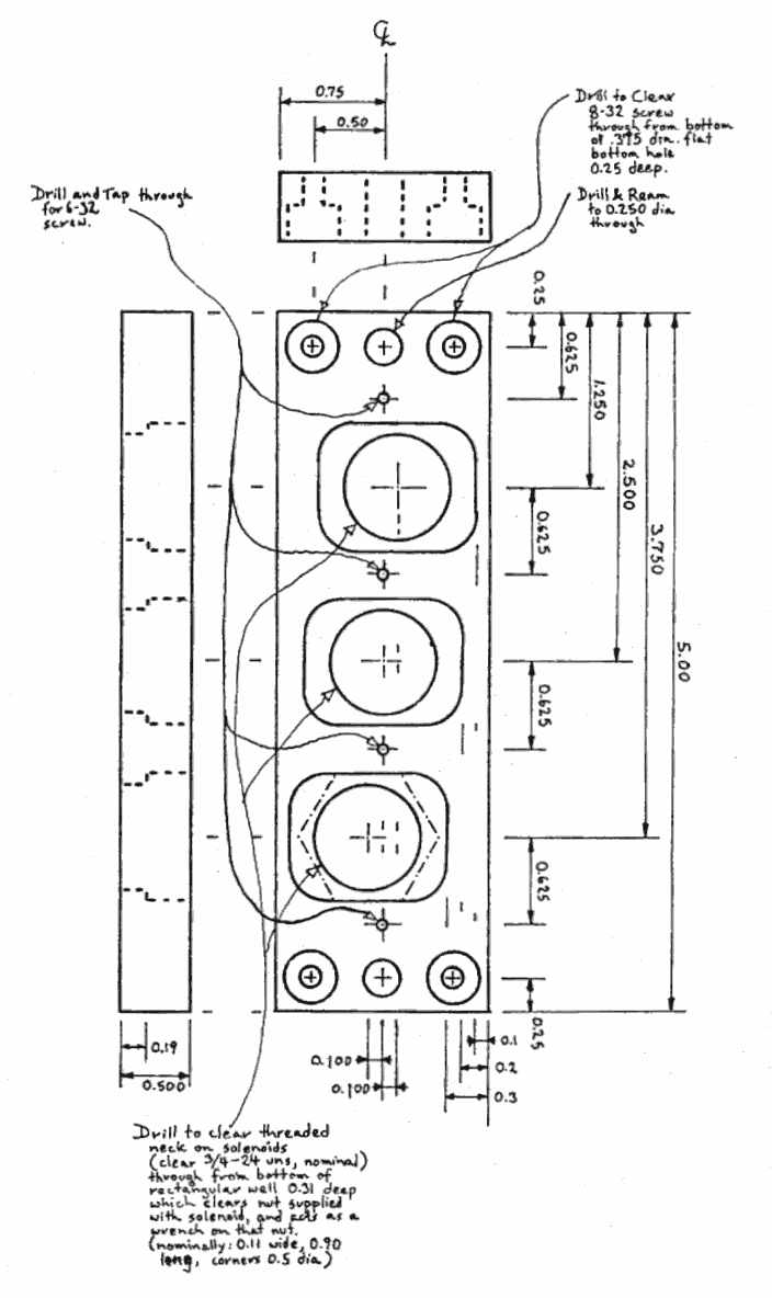
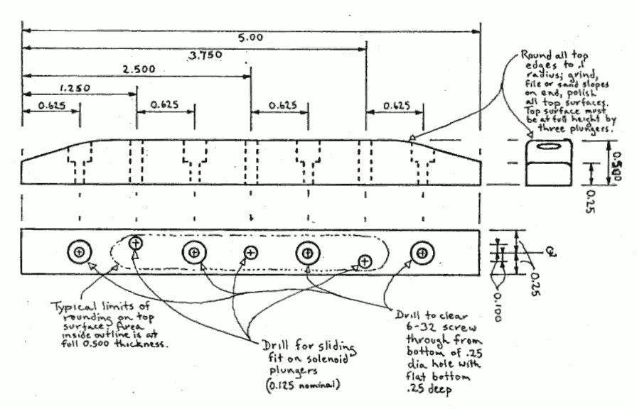
Mount solenoids loosely in holes in top plate, from inside with nuts in wells on outside.
Mount die guide on top plate with 4 6-32 × 3/4 cap screws, check for free sliding of solenoid plungers.
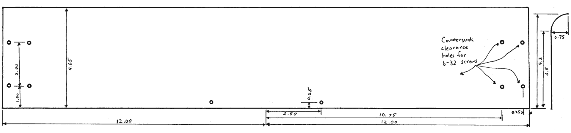
Mount bottom plate between ends of end plates, well facing up, 2 mounting holes in side facing opposite the ramps on the end plates, with 4 8-32 × 3/4 screws.
Tighten all but the clamp bolts, attach terminal strip to side of bottom plate with 2 4-40 × 3/8 screws.

Carriage End Plates (3.2.7.1)
(2 required)
Material: 1/2 inch aluminum plate)
Note: Left end plate shown, right end plate is mirror image.
Do not install cable at this point!
link to sketch showing end plate, bearings, cable attachment
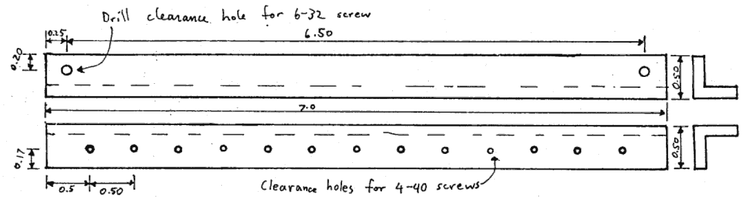
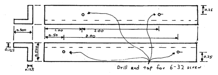
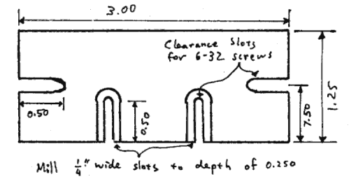
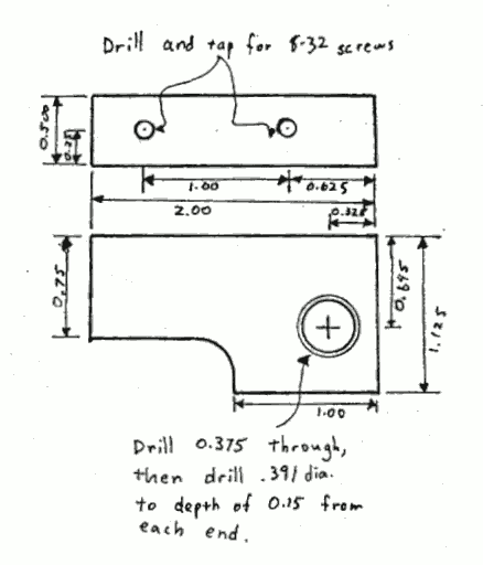
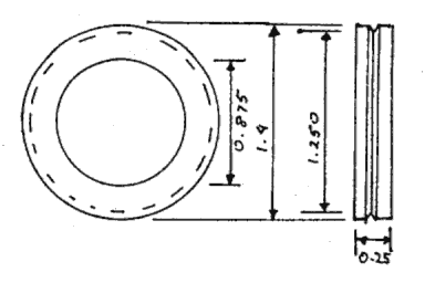
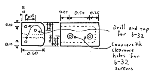
Make 4 0.50 × 0.25 dia pins to fit in slots in Carriage End Plates.
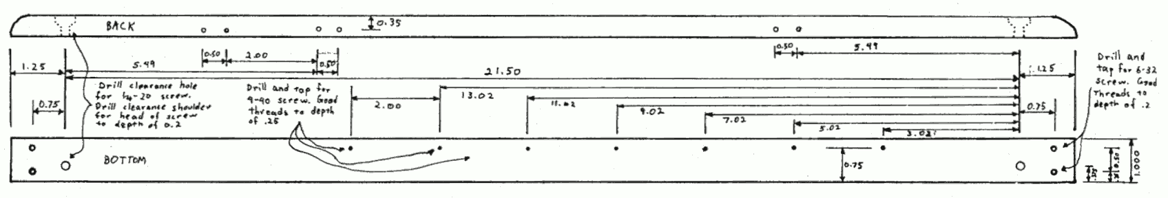
The upper pin in each end plate is held by 2 6-32 × 3/8 screws.
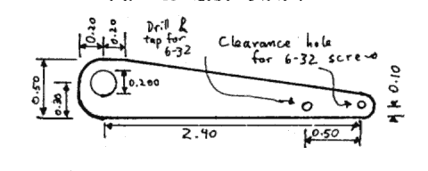
This pin sets the radius of the bend in the cable.
The lower pin in each end plate is adjusted by a 10-32 × 1/4 allen head set screw.
This pin is used for fine adjustment of cable tension and carriage position.
Insert ball bushings in large holes in end plates.

Carriage Clamp Bolts (3.2.7.1.1)
(2 required)
Made from 1/4-20 × 3/4 brass bolt.
Drill through bolt 1/16 dia, just under head.
If the resulting hole is not tangent to the plane of the underside of the head, use washers to get this effect.
link to drawing, brass bolt with hole drilled just under head

Carriage Top Plate (3.2.7.3.1)
(Material: 1/2 inch aluminum plate)
link to drawing, 5 by 1.5 by 1/2 in. block with 9 holes

Carriage Die Guide (3.2.7.3.2)
(Material: 1/2 inch sq. brass bar)
link to drawing, 5 by 1/2 by 1/2 bar with 7 holes, tapered ends

Front Panel (3.3.1)
Material: 1/16 aluminum
link to drawing, 24 by 4.65 in. plate, 10 holes, long edge bent

Side Panels (3.3.2)
(2 required, mirror images)
Material: 1/16 aluminum

link to drawing, 12.8 by 4.32 plate, 4 holes, ends bent inward

Front Panel Bracket (3.3.1.1)
link to drawing, 1/2 in. angle, 7 in. long, 4 holes

ComputerSupportPlate (3.4)
Matrial: 1/8" Aluminum
link to drawing, 24 by 7.25 plate, 18 holes, 3 complex notches

Card Guide Bracket (3.4.1.2.1)
(2 required)
link to drawing, 1/2 in. angle 5 in. long, 2 notches, 3 holes

Card Guide (3.4.1.2.2)
(2 required)
Material: plastic
link to drawing, 5 by 1/4 by 0.3 in, 2 holes and a long slot

Card Retainer (3.4.1.2.3)
Cut and bend a piece of 1/16" aluminum in this shape.
link to drawing, 0.9 by 0,5 plate, 1 hole, 1 notch, 2 bends

Toggle Switch Mount (3.4.2.1)
link to drawing, 1/2 in. angle 2.5 in long, 5 holes

Hinge (3.4.8)
(2 required)
Material: steel
This does not need to be a high precision item. Undrilled hinges meeting these specifications are available commercially.
link to drawing, 2 by 1 in. hinge (leaf dimensions) with 4 holes