A Critique of the Braille PrinterWe could have done a better job
Part of
the Braille Printer Web Pages
|
A Critique of the Braille PrinterWe could have done a better job
Part of
the Braille Printer Web Pages
|
Looking back at our 1980 Braille printer design from 2022, I feel there is little to apologize for. I think we did a very good job, on the whole. There are, however, things we could have done better at the time.
After discussing those, I will briefly discuss how our design would change if we were doing it today.
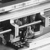
The solenoids we used to emboss the Braille dots had a throw of on the order of an inch, when we only used about 1/8 inch of throw. Solenoids offering the same force with a shorter throw were probably available and it is highly likely that short-throw solenoids offering the same force would be lighter, reducing the weight of the carriage and therefore reducing the torque needed by the motor to achieve any particular speed.
The entire carriage assembly was a very conservative design, and that means it was heavier than needed. We could certainly have cut significantly more metal off of the carriage. As with smaller solenoids, this would also lead to higher performance.
Similarly, the end plates supporting the carriage ways and platten were uniformly 1/2 inch thick. We needed this thickness for rigidity, but we could have removed quite a bit of metal from the end plates without sacrificing rigidity, either by drilling lots of holes or by milling large areas thinner. This would not improve performance, but it would help reduce the weight of the printer.
40 years ago, Andrew Appel recalls me saying something like "We should probably not have used a stepping motor. Daisy-wheel printers use a non-stepping motor, with a feedback sensor to detect how fast / how far the carriage moved. This would probably be able to move the carriage faster, at lower cost. But the control program would have been more work."
In retrospect, this critique was wrong. I have since learned that stepping motors and servomotors are interchangeable. There is no reason to expect better performance from one than from the other, so long as the control system can model the physics of the mechanical system. The tradeoff is basically between the cost of position feedback for a servosystem versus a computational model of the system for the stepper.
The computational model for our Braille printer is simple because the inertia of the carriage and the motor rotor are fixed, and the elasticity of the tendon drive is close to constant. As a result, we were able to boil the computational model down to a table saying how long to wait for the next step, and what the velocity will be after that delay as a function of the current velocity and steps until destination. We didn't fine tune our table very well, but we could have. I've had good success with that model in other applications.
We used linear current limiters, the only kind I understood at the time. While it was significant that I used transistors and not simple passive resistors for this, we could have done much better. Had we used switching limiters, we probably could have reduced the power consumption of the printer by an order of magnitude.
Reduced power consumption would not only reduce the waste heat we had to blow out of the case with an exhaust fan, but it would also reduce the size of the 24-volt power supply. Those big transformers made up a big part of the awkward weight of the printer. A switching current limiter would probably have allowed us to eliminate one of the two big transformers.
The +/- 12 volt power was only needed for one reason: To power the serial data line. Nothing else in the entire system needed these voltage levels. The transformer we used could provide an amp, but we only needed milliamps! A tiny transformer would have sufficed, but we were too lazy to search for one and used the first relatively small transformer we found.
Our +8 power supply was also oversized, but not by nearly as much. Downsizing these power supplies would have shaved more off of the printer's weight
Watching the printer in operation, I recall seeing the stainless steel cable used for carriage positioning vibrate like a guitar string, with, at times, a surprising amplitude. After extended use, this would almost certainly lead to metal fatigue at the point where the cable was anchored to the carriage. Some provision for damping this vibration would be extremely helpful.
The pullies on the end plates were anchored on axles set in slots in the end plates. If we had milled these slots a bit deeper to allow a rubber pad between the bar and the axle, this could have provided some damping. Similar treatment of the bar at the cable anchorage on each end of the carriage could have provided more damping.
Note that reduced resonance could also have contributed to higher performance. The reason is that resonance makes precise position control difficult, and it may have been a factor that limited the rate at which we could accelerate and decelerate the carriage.
The external control switch we offered, selecting between literal Braille for software listings and English Braille mode was not enough. Why did we put the switch to select between Grade 1 and Grade 2 inside the printer? Really, what we should have done is put a 3-way switch on the cover, up for computer mode, middle for Grade 1 and down for Grade 2.
What we designed was a prototype, well enough made that it was actually useful, but a prototype nonetheless. If we were thinking about a production run, even just a few tens of machines, we would have used more bent and folded sheet metal instead of shapes milled from blocks. The bottom plate of the carriage, the microswitch mounting block, and paper advance motor mount would be the first parts to make this way.
If we were starting over today, most of the mechanical design could stay as it was, perhaps improved as suggested above, but we would use a tiny single-board microcontroller such as the Arduino. It might be reasonable to use something like a Raspberry PI, but that has a heavy-weight operating system (usually some flavor of Linux) making it a poor choice for real-time control.
The software architecture we used on the Z-80 based Chromemco SBC would work just as well today, with a single background process doing ASCII to Braille translation while interrupt driven foreground processes handle both the communications line and the real-time control of the motors and solenoids.
Of course, today, RS-232 asynchronous serial data is rarely used. Instead, we'd have to support a USB port or perhaps some wireless protocol. Support for those is much messier than support for RS-232, and this might push the design to include a heavy-weight processor like the Raspberry, with real-time control offloaded onto a separate microcontroller like the Arduino.
It would also make good sense to 3-D print the carriage parts and the end plates supporting the ways, using a high-rigidity plastic. Alternatively, CNC machining would allow removal of all but the essential metal from the carriage and end plates at a reasonable cost.